


Programming with a Series 200/300 Computer
106
Service Request and Serial Poll
The fault and mask registers, when used in conjunction with the service request and serial poll functions, allow you to
select which conditions can cause computer interrupts. The fault and mask registers can also be used independently of the
serial poll or service request if so desired. The following example shows how to enable an interrupt to the computer in the
case of an overvoltage condition. After the interrupt has occurred, this example includes an interrupt routine that conducts a
serial poll to determine on which output the overvoltage occurred. Note that this example assumes that terminal block
external OV trip lines are not wired together.
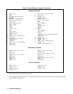
10 ASSIGN @Ps TO 705
20 COM /Ps/ @Ps
30 OUTPUT @Ps;’’CLR;UNMASK1,8;UNMASK2,8;SRQ1’’
40 ON INTR 7,1 CALL Err _ trap
50 ENABLE INTR 7;2
60 OUTPUT @Ps;"OVSET1,4;OVSET2,4"
70 OUTPUT @Ps;’’VSET1,5;VSET2,5"
80 Lbl: GOTO Lbl
90 END
100 !
110 !
120 SUB Err _ trap
130 OFF INTR
140 COM /Ps/ @Ps
150 IF BIT(SPOLL(@Ps),0) THEN
160 OUTPUT @Ps;’’OUT1,0;OVRST1"
170 PRINT "OVERVOLTAGE ON OUTPUT #1"
180 END IF
190 IF BIT(SPOLL(@Ps),1) THEN
200 OUTPUT @Ps;"OUT2,0;OVRST2’’
210 PRINT ’’OVERVOLTAGE ON OUTPUT #2"
220 END IF
230 OUTPUT @Ps;’’FAULT?1;FAULT?2’’
240 SUBEND
LINE 10: Assigns the I/O pathname to the power supply.
LINE 20: Declares a common block for the I/O pathname. The COM statement must be used for the @Ps variable
to preserve its value for use in the service routine.
LINE 30: Returns the power supply to its power on state, unmasks output 1’s and output 2’s OV status bits to
generate faults, and enables the service request capability on all outputs.
LINE 40: Defines interrupt at interface 7, with GP-IB priority 1.
LINE 50: Enables interrupt at interface 7 for service request type interrupts only.
LINE 60: Sets the overvoltage of outputs 1 and 2 to 4 volts.
LINE 70: Sets the voltage of outputs 1 and 2 above the OV setting so that both outputs will overvoltage when the
program is run.
LINE 80: Waits for the computer to receive the interrupt. This simulates conditions that would normally exist when
a program is running.
LINE 120: Defines the error handling routine.
LINE 130: Disables interrupt capability while processing.
LINE 140: Brings in the common block for the I/O pathname.
LINE 150-180: Conducts a serial poll. If bit 0 in serial poll register indicates a fault for output 1, output 1 is disabled and
the overvoltage circuit is reset.
LINE 190-220: Checks bit 1 in serial poll register for a fault on output 2. If true, output 2 is disabled and the overvoltage
circuit is reset.
LINE 230: Reads fault registers to clear FAU bits in serial poll register.