


Installation28
Power Cord
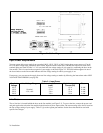
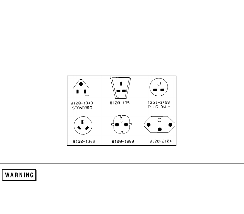
The power supply is shipped from the factory with a power cord that has a plug appropriate for your location. Figure 2-4
shows the standard configuration of plugs used by Agilent Technologies. Below each drawing is the Agilent part number
for the replacement power cord equipped with a plug of that configuration. If a different power cord is required, contact the
nearest Agilent Technologies Sales and Service office.
For your protection, the National Electrical Manufacturer’s Association (NEMA) recommends that the instrument panel and
cabinet be grounded. This power supply is equipped with a three-conductor power cord; the third conductor being the
ground. The power supply is grounded only when the power cord is plugged into an appropriate receptacle. Do not operate
this power supply without adequate cabinet ground connection.
Figure 2-4. Power Cord Plug Configurations
SHOCK HAZARD. Connect the power cord to a grounded receptacle before you connect any
external floating voltages to the supply.
The offset pin on the standard three-prong power cord connector is the ground connection. If a two contact receptacle is
encountered, it must be replaced with a properly grounded three-contact receptacle in accordance with the National
Electrical Code, local codes and ordinances. The work should be done by a qualified electrician.
Line Voltage Conversion
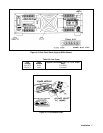
You can change the supply to accept 100 V, 120 V, 220 V and 240 V ac input by adjusting the voltage selector card located
inside of the line module (see Figure 2-3). After you have changed the line voltage, refer to Table 2-2 and check that the
fuse inside the line module is the correct fuse for that line voltage. The procedure is as follows:
1. Turn off power and remove the power cord from the ac input socket on the back of the power supply.
2. To open the line module, move the plastic door on the module aside. If your line voltage change requires a change in the
rating of the fuse, rotate FUSE PULL to the left and remove the fuse.
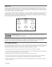
3. Grasp the voltage select pc board with a pair of needle-nose pliers and slide it out of its slot.
4. To select a voltage, orient the pc board so that the desired voltage appears on the top left side of the board. Push the
board all the way back into its slot. The desired line voltage must be visible when the board is installed.
5. Install the correct fuse in the door of the line module if your line voltage change also requires a change in the rating of
the fuse (see Table 2-2).