


Output Connections and Operating Information
59
Series Operation
SHOCK HAZARD. Floating voltages must not exceed 240 Vdc. No output terminal may be more
than 240 Vdc from chassis ground.
Connect in series only outputs that have equivalent current ratings. Each output has a reverse voltage
protection diode across its output terminals. The current conducted by this diode is not internally
limited by the output. Therefore, never connect an output in such a way that this
diode will conduct
current in excess of the rated current of the output since damage could result.
Connecting outputs in series provides a greater voltage capability than can be obtained from a single output. Because the
current is the same through each element in a series circuit, outputs connected in series must have equivalent current
ratings. Otherwise, the higher rated output could potentially damage the lower rated output by forcing excessive current
through it under certain load conditions.
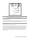
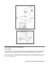
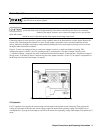
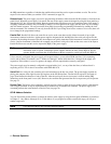
Figure 4-13 shows an example of how to connect two outputs in series to a single load with local sensing. This
configuration applies to both CV and CC operating modes. Connecting the + load lead of output 2 directly to the
- V terminal of output 1 completes the series connection between the two outputs. Connecting the + S terminal of output 2
directly to the - S terminal of output 1 and removing the sense jumper (between + S and + V) on output 2 compensates for
the IR drop in the load lead from output 2 to output 1.
Figure 4-13. Series Connections with Local Sensing
CV Operation
For CV operation, first program the current setting of each output to the desired current limit point. Then program the
voltage of each output so that the sum of both voltages equals the total desired operating voltage. The simplest way to
accomplish this is to program each output to one half of the total desired operating voltage. Both outputs will operate in CV
mode.