


General Information
15
Output Boards
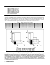
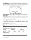
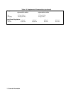
The output boards are linear dc power supplies. Each isolated output operating boundary curve is shown in Figure 1-1.
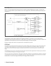
The ac input to each output board is rectified and applied to a regulator circuit. Each output board employs series regulation
techniques. A regulator element is connected in series with the load and operates in the linear region (between saturation
and cutoff) of the transistor characteristic curve. Regulation is achieved by varying the conduction of the series element in
response to a change in line voltage or circuit load.
The output board receives digital signals from the GP-IB board and converts them to analog signals which program the
output voltage, current, and overvoltage values. The output may be programmed remotely over the GP-IB using commands
(see Chapter 5) or locally from the supply’s front panel using the control keys (see Chapter 6).
The output board can be commanded to send measurement and status data back over the GP-IB and/or front panel. The data
is sent back via the supply’s GP-IB board. GP-IB readback capabilities include output voltage and current, present and
accumulated status, and all programmed settings. The front panel LCD display can indicate the output voltage and current,
the supply’s GP-IB address, error messages, and programmed values. Annunciators on the front panel indicate the operating
status of the selected output (output board).
Specifications
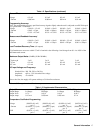
Table l-2 lists the performance specifications for the Agilent 662xA power supplies. Performance specifications describe
the instrument’s warranted performance. The service manual, Option 9l0, contains procedures for verifying the
performance specifications.
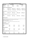
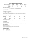
Table 1-3 lists the supplemental characteristics for the Agilent 662xA supplies. Supplemental characteristics are type-tested
or typical values, which are based on a product sample and, while representative, are not guaranteed.
Qualifying Conditions
All performance specifications apply over the full operating temperature range of the power supply (0 to 55°C) unless
otherwise specified. All regulation, accuracy, etc. specifications are plus or minus the values listed. All measurements are
made at the rear terminals of the supply with a resistive load and local sensing unless otherwise specified. Voltage
measurements are made from the + S to the - S terminals. Overvoltage measurements are made from the + V to the - V
terminals. + Current refers to the output acting as a current source while - Current refers to the output acting as a current
sink.
Definitions
Load effect
: Maximum steady state change in the regulated output parameter due to a change in load resistance on the
output in question.
Source effect: Maximum steady state change in the regulated output parameter due to a change in the source voltage
within rated values.
Cross regulation: Maximum steady state change in the regulated output parameter due to a change in load resistance on
any other output(s).
Programming accuracy: (Calibration temp ± 5°C) Maximum difference between the programmed value and the actual
output.
Readback accuracy: (Calibration temp ±5°C) Maximum error in reading back an output parameter. Expressed as a
percentage of the reading, plus a constant.