


Output Connections and Operating Information
46
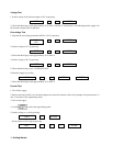
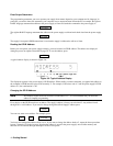
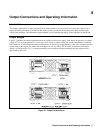
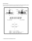
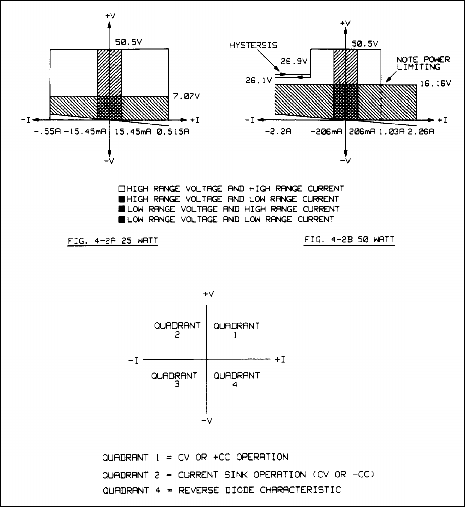
Operating Quadrants
Figures 4-2A and 4-2B show the operating locus of your power supply in three quadrants. The area in quadrant 1 shows the
operating locus defined by the voltage and current settings of each output. The area in quadrant 2 indicates the locus where
each output can operate as a current sink. You cannot program current limit values in quadrant 2.
Figure 4-2. Typical Output Range Characteristics