


Operating and maintenance instructions Section 1: Introduction
3-9008-701 Rev J January 2015
General 1
11
12
13
14
15
16
Section 1: Introduction
1.1 General
This manual is designed to provide information and guidance to personnel responsible for the
operation and maintenance of the Compact Prover. The content of this manual is intended to
describe the normal operational characteristics of the Compact Prover. By necessity, this
manual is written for standard provers. It does not include specific information pertinent to
specially designed items or non-standard equipment. Operating and Maintenance Instructions
for special equipment will be supplied as necessary.
The Compact Prover is not a stand-alone system. The prover requires the use of an operating
computer that is capable of Dual Chronometry Pulse Interpolation. The operating computer will
process and summarize all proving data. Refer to the Operation section of this manual for more
information.
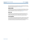
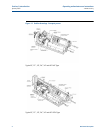
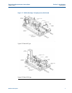
1.2 Description
The Compact Prover provides improved accuracy, rapid operation and continuous flow for
performance testing, or ‘proving’, of liquid flow meters in an operational line. Modern
electronics permit exact time determination and pulse counting, which provides high accuracy
proving with a smaller volume and fewer flowmeter pulses than any previous proving
technology.
Because of its reduced size and a unique patented piston design, which includes an internal
poppet valve, the Compact Prover can be easily installed in most operational lines and operated
with minimal disturbance to flow. The prover’s internal design incorporates an inherent fail-safe
feature constructed to assure uninterrupted liquid flow.
The Interface Enclosure contains a printed circuit board which conditions the signals generated
by the prover. The operating computer, which is typically located in a control room, receives
these signals and generates data from the proving passes. This data can be printed for manual
implementation to the process line flow meter. Some proving applications can be programmed
for automatic implementation.
A typical proving run should generate the following raw data:
1. The exact time interval, in seconds, for the certified volume of the prover to be
displaced.
2. The exact time interval, in seconds, to tabulate flow meter pulses.
3. The exact number of whole meter pulses generated by the liquid displaced during the
proving run.
Typical data given by the operating computer include:
• Frequency: Flowmeter pulses/second, Hz
• Flow rate: Units of volume/minute or hour (Can be gpm, bph, lpm or m /hr.)
• K-Factor: Flowmeter pulses/unit of volume