


Operating and maintenance instructions Section 4: Maintenance
3-9008-701 Rev J January 2015
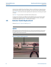
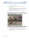
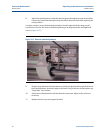
Detector Switch Replacement 71
12. Upon completion of volume certification see Section 2.4.
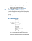
If the switch replacement procedure has been performed correctly, the replacement switch will
be within 0.001 inches (.0254 mm) from the original switch position. The formula for cylinder
volume can be used to determine the degree of change in the water draw volume.
Example for a 12” prover:
Water draw volume change for 0.001 inch of switch movement =
π (d/2) (0.001) = π (12.25/2) (0.001) = 0.1178 in
3
Since 15 gallons = 3465 in
3
:
The percent change = 0.1178/3465(100) = 0.0034%
This percent change in the water draw volume is well within the 0.02% allowed.
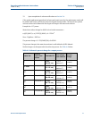
Similar changes can be expected in the other size provers. See Table 4-4 below.
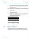
Table 4-4 Volumetric percent change for compact provers
Prover size
Nominal
prover base
volume
Flow tube I.D.
Base volume
from nominal
Percent
change
8”
5 gal (20 L)
8.250”
(20.955 cm)
1,155 in
3
(20000 cm
3
)
0.0046%
(.0044%)
12” Mini
10 gal (40 L)
12.250”
(31.115 cm)
2,310 in
3
(40000 cm
3
)
0.0051%
(.0048%)
12”
15 gal (60 L)
12.250”
(31.115 cm)
3,465 in
3
(60000 cm
3
)
0.0034%
(.0032%)
18”
30 gal (120 L)
17.500”
(44.450 cm)
6,930 in
3
(120000 cm
3
)
0.0035%
(.0033%)
24”
65 gal (250 L)
25.500”
(64.770 cm)
15,015 in
3
(250000 cm
3
)
0.0034%
(.0033%)
34”
100 gal (400 L)
34.00”
(86.360 cm)
23,100 in
3
(400000 cm
3
)
0.0039%
(.0037%)
40”
170 gal (650 L)
40.00”
(101.60 cm)
39,270 in
3
(650000 cm
3
)
0.0032%
(.0032%)