


66 Hydraulic Cylinder and Hydraulic Seal Support
Section 4: Maintenance Operating and maintenance instructions
January 2015 3-9008-701 Rev J
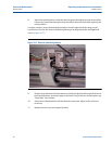
18. Check the bushing in the actuator seal support for clearance on the actuator rod.
Correct clearance is .002 to .005 inch (.051 to .127 mm). If clearance is excessive,
consult the factory for replacement.
Assembly
In the following procedure where lubrication of parts is recommended, it should be noted that
excessive amounts of lubrication should be avoided as the base volume of subsequent water
draw could be affected.
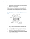
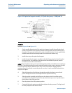
Reference Figure 4-11 and Figure 4-12.
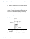
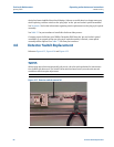
1. Install the inner seal, the backup washer, the outer (larger) seal and retaining ring into
the hydraulic seal support. Open ends of both seals are to face the flow tube.
2. Install the o-ring on the hydraulic seal support holding it in place with a small amount of
lubricant.
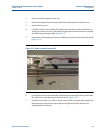
3. Install the hydraulic seal support on the inlet flange by sliding it onto the actuator shaft.
Apply a small amount of grease to the actuator shaft at the beveled edge to ensure the
seals do not fold over. Align the support with the weep hole pointing down. A slight
rotation of the support may be necessary to align the bolt pattern between the support
and the inlet flange. Secure the support with the socket head screws.
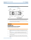
4. Install the downstream flange of the hydraulic cylinder by sliding it onto the actuator
shaft. Apply a small amount of grease to the actuator shaft at the beveled edge to
ensure the seals do not fold over. Align the hydraulic ports in the flange with the
hydraulic hoses and the stud holes with those in the hydraulic seal support.
5. Install the cushion on the actuator shaft with the chamfer facing the flow tube.
6. Install new seals on the actuator piston and install the piston to the actuator shaft. Use
care not to damage the o-ring in the bore of the actuator piston with the shaft threads
by threading it onto the actuator shaft.
7. Install the locking nut and tighten with an impact wrench. The locking nut should be
tightened until the actuator piston is unable to turn.
8. Install the two (2) o-rings on the end of the hydraulic cylinder tube. Pay attention to the
flat o-ring as it must be installed with the flat side against the shoulder on the end of the
tube. Then install the round o-ring.
9. Install the hydraulic cylinder tube over the actuator piston. Use a smooth piece of
plastic to compress the piston seal as necessary. Slide the tube up to within
approximately 1” of the downstream flange. Be sure the o-rings are in place.
10. Install the hydraulic cylinder tie rods into the tee of the inlet flange. If the rods have
longer threads on one end, install these ends in the tee.
11. Install the o-rings onto the upstream end of the hydraulic cylinder tube. These o-rings
are installed in the same manner as in step 8.
12. Install the upstream flange of the hydraulic cylinder. Also install the bracing plate from
the support bar if so equipped.