


18 12 or 24V DC Interface Board
Section 2: Installation and set-up Operating and maintenance instructions
January 2015 3-9008-701 Rev J
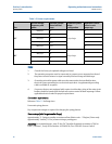
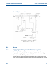
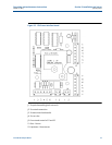
2.2.3 12 or 24V DC Interface Board
There are two (2) different styles of interface boards: 12V DC and 12/24V DC. See Figure 2-3 and
2-4. The power required for the interface board is supplied through the control cable. The DC
power source is typically located in the control room or can be supplied from the operating
computer if so equipped. See the electrical schematic provided with the prover documentation
package for proper connections of the control cable.
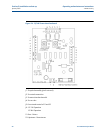
The 12V interface board is designed to operate on 12V DC (±15%, 100mA max). The 12/24V
interface board can operate on either 12 (±15%, 100mA max) or 24V DC (±15%, 250mA min)
depending on the configuration of jumper J6, see Figure 2-4. For 12V operating power, J6 must
be jumpered to pins 1 and 2. For 24V operation, J6 must be jumpered to pins 1 and 3. If
operating voltage is applied incorrectly, there is an integral fuse for board protection. In the
event that the fuse is blown, confirm the configuration of jumper J6 and replace the fuse with a
100mA, fast blow fuse ONLY.
The 12/24V interface board is installed in all compact provers made after September 2002. It
may also be used to replace the 12V interface board on older model provers. Contact a Daniel
representative if you are unsure which interface board your compact prover is equipped with or
if you need assistance replacing the old 12V board with the new 12/24V board. Request service
bulletin SE101 for detailed retrofit information.
Important:
Do not handle electronic-sensitive equipment without an ESD grounding wrist-strap. Failure to
use an anti-static grounding device could cause damage to the compact prover electronics and
render them inoperable.