


70 Detector Switch Replacement
Section 4: Maintenance Operating and maintenance instructions
January 2015 3-9008-701 Rev J
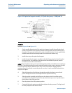
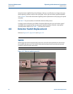
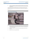
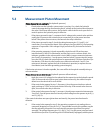
8. Adjust the switch position so that the detector passes through the center of the switch.
If necessary, loosen the bearing housing and slide it along the shaft while adjusting the
switch position.
It may be necessary to pry the bearing housing free from the optical shaft by using a small
screwdriver in the rear slot. Return the bearing housing to its original position and tighten all
screws. (Figure 4-15)
Figure 4-15 Detector switch adjustment
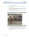
9. Plug the new switch into the main harness, feeding the plug back through the frame to
the original location. Anchor the plug to the frame using a new wire tie and replace any
“hoop-style” wire anchors.
10. Verify wires will not interfere with the detector movement. Adjust and/or anchor as
necessary.
11. Replace the dust cover and support bracket.