


60 Optical Seal Support
Section 4: Maintenance Operating and maintenance instructions
January 2015 3-9008-701 Rev J
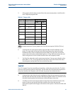
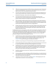
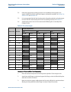
17. Torque the tie rod nuts to the values specified inTable 4-2 for the proper prover size.
Torque all the tie rod nuts in a ‘criss-cross’ pattern.
18. It is recommended that the leak check procedure be performed after seal replacement
to assure that the measurement piston seals are working correctly. See Section 4.1.
19. A hydrostatic pressure test is also recommended following the re-assembly of the
compact prover.
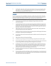
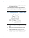
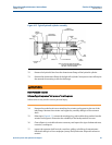
4.4.2 Optical Seal Support
To determine if the optical seal support is in need of repair, check the weep hole at the bottom
of the seal support. If line product is leaking from the weep hole, the seals internal to the
support should be inspected for possible replacement.
Disassembly
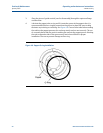
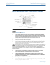
Reference Figure 4-9.
1. Remove the bracket securing the optical switch cover.
2. Remove the optical switch cover and o-ring.
3. Disconnect the main plug to the optical switch wiring harness near the seal support.
Remove the ‘hoop style’ wire anchor that holds it to the optical frame.
4. Loosen the clamping screws that hold the flag assembly to the detector shaft.
5. Carefully slide the flag assembly off of the shaft. DO NOT damage or disturb the
position of the optical switches. Be careful not to strike them with the flag when it is
removed.
6. Remove the optical assembly by removing the four (4) socket head screws holding it to
the seal support. Temporarily place the optical assembly where it will not get damaged.
HIGH PRESSURE HAZARD
Release all pipeline/process fluid pressure from the prover.
Failure to do so may result in serious personal injury.