


74 Interface Signals
Section 5: Troubleshooting Operating and maintenance instructions
January 2015 3-9008-701 Rev J
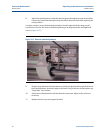
interface board whenever the flag is within either of the optic volume switches. This signal is
present between pins 2(-) and 7(+) of J-2.
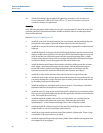
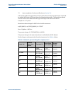
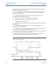
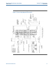
Figure 5-1 is a timing diagram that shows the interface signal operation that the operating
computer will see coming from the compact prover during a proving cycle. The diagram
positions are explained below.
t1- Computer sends RUN signal low, hydraulics go into bypass, poppet closes and
measurement piston and flag start downstream.
t2 - Flag clears upstream (stand-by) switch; upstream signal goes high.
t3 - Flag enters the first volume switch sending detector signal low.
As flag exits switch, signal goes high.
t4 - Flag enters the second volume switch sending detector signal low. As flag exits switch,
signal goes high.
t5 - Computer sends RUN signal high, hydraulics are activated, poppet opens and
measurement piston starts upstream.
t6 - Flag enters the second volume switch sending detector signal low. As flag exits switch,
signal goes high. Computer ignores pulses during return stroke.
t7 - Flag enters the first volume switch sending detector signal low. As flag exits switch, signal
goes high. Computer ignores pulses during return stroke.
t8 - Flag enters upstream (stand-by) switch, upstream signal goes low. Compact prover
remains in this condition until RUN command is received from computer.
Figure 5-1 Prover signal timing