


Operating and maintenance instructions Section 4: Maintenance
3-9008-701 Rev J January 2015
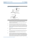
Water draw procedure: (Reference Figure 4-4 and notes on page 47) 45
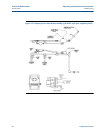
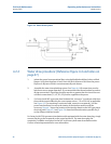
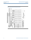
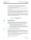
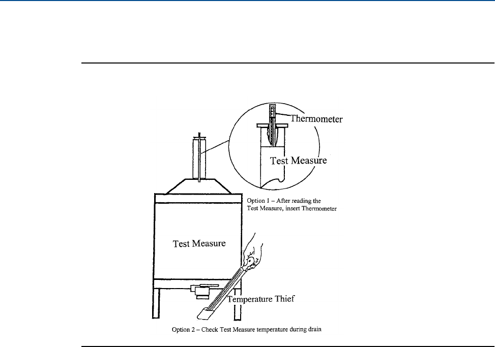
Figure 4-5 Test measure temperature stabilization
15. Slide optical assembly cover back to expose the second optical volume switch and the
ends of the invar rods. Measure and record the temperature at Td (invar rod
temperature) using the digital thermometer and contact probe. Replace the optical
assembly cover. See Note 4 on page 47.
16. Record the water level shown on the calibrated section of the test measure. This
measurement must be taken from the bottom of the meniscus inside the glass tube.
17. Record Tm, the temperature of the test measure (i.e. the water temperature inside the
test measure). Open valve W3 momentarily, allowing about ½ gallon (2 liters) of water
to drain out, and measure the temperature of the drained water with the temperature
thief. (Figure 4-5).
18. Open valve W1 momentarily to replace the water drained from the test measure. This
will allow the flag to proceed downstream just beyond the second optical volume
switch.
19. For the Upstream (procedure a) and Combined (procedure c) water draw: Verify valve
W1 is closed and reset the valves for upstream flow (V1 and D2 open; V2 and D1
closed). Proceed to step 20.
20. For the Downstream (procedure b) water draw: Return to step 10 and repeat the
process for as many Downstream cycles as desired. See Note 2 on page 47. Be certain
the optical assembly cover is in place and toggle the UPSTREAM/DOWNSTREAM switch
(S2) on the interface board to the upstream position. Actuate the RUN/RETURN switch
(S1) to the run position. (See Note 3 on page 47-14.) This will open the solenoid valve
(SV) and the measurement piston will begin to move upstream. Throttle valve W3, if