


Operating and maintenance instructions Section 4: Maintenance
3-9008-701 Rev J January 2015
Optical conversion kit 67
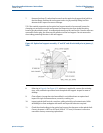
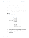
13. Install the four nuts on the hydraulic cylinder tie rods. Double check the o-rings on each
end of the hydraulic cylinder tube to make sure they are in place. Tighten the nuts
evenly to bring the hydraulic cylinder tube and flanges together. Torque to
specifications listed inTable 4-3.
Tip: To ensure proper alignment of the hydraulic cylinder, use a level to verify the alignment with
the flow tube.
14. Connect the nitrogen supply hose from the spring plenum and the hydraulic hoses to
the hydraulic cylinder.
15. Install the operating handle on the nitrogen shut-off valve. Open the shut-off valve and
check for and eliminate any leaks.
16. Once the prover is fully assembled, check the hydraulic reservoir for proper level. Turn
on the power and start the hydraulic system motor. Check for and eliminate any
hydraulic system leaks. Once all air is eliminated from the hydraulic system, turn off the
motor and re-check the reservoir for proper level.
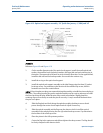
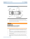
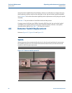
4.5 Optical conversion kit
Compact provers purchased prior to June 1989 are designed with a ‘shotgun’ style optical
assembly. These older provers may be retrofitted to accommodate the new ‘plug style’ optical
assembly. Installation instructions are provided with the kit. Switch replacement on the new
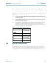
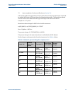
Table 4-3 Hydraulic cylinder tie rod nut torque
Prover size Torque value
8”
25 ft lbs (34 Nm)
12” Mini
45 ft lbs (61 Nm)
12”
45 ft lbs (61 Nm)
18”
125 ft lbs (170 Nm)
24”
220 ft lbs (299 Nm)
34”
600 ft lbs (814 Nm)
40”
1,400 ft lbs (1900 Nm)