


Operating and maintenance instructions Section 5: Troubleshooting
3-9008-701 Rev J January 2015
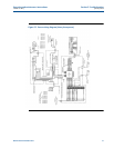
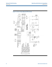
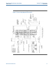
The auto plenum adjust panel 81
Correction procedure:
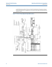
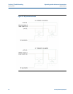
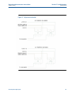
Determine which type of computer output is being used and compared this to the wiring at the
relays.
1. If necessary, refer to the prover’s wiring diagram.
2. If +24V DC is common to both relays and the negative (-) from the coil of each relay
goes back to TB1, they are wired for sinking current.
3. If the DC negative (-) is common to both relays, and the positive (+) wire from the coil of
each relay goes back to TB1, they are wired for driving current.
4. Correct the wiring as needed for the type of computer signal being used.
5. See Figure 5-6 and Figure 5-7 for simplified diagrams.
6. Restore power and test signals again for correct operation.
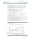
7. If the solenoids begin to work as desired but the proving computer still automatically
aborts the proving sequence, be certain the plenum “time out” (the time set within the
computer’s configuration to charge/vent the plenum) is long enough to fill or vent the
plenum. Due to the small orifice of the solenoid valves, it can take some time to adjust
the plenum pressure to the needed value. Manual charging or venting of the plenum
may be necessary.