


10 Technical data
Section 1: Introduction Operating and maintenance instructions
January 2015 3-9008-701 Rev J
Notes:
1. Consult the factory for optional voltages not listed.
2. The operating computer must be connected to a power source separate from that of
the prover to avoid variance in signal caused by line load charge and discharge.
3. Grounding wire within power cable must be connected to the installed location
electrical system grounding bus or electrical equivalent. A supplemental grounding
cable is available as an option.
4. For provers that are not equipped with a main circuit breaker, sizing of the main circuit
breaker should be based upon the hydraulic system motor full load amperage. Follow
applicable electrical codes for proper requirements.
Connection requirements:
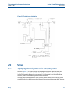
Reference Table 1-2 for flange sizes
Pneumatic spring plenum:
Dry compressed nitrogen is required for charging the spring plenum.
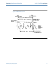
Pressure drop: (Inlet flange to outlet flange)
Approximately 11.2 psig on gasoline at maximum flow (Metric units - .79 kg km ) Piston only:
Approximately 3 inches (7.6 cm) of water during a proving pass.
Approvals: For standard provers, sizes 8” thru 24” Canadian Standards Association (CSA) for
Class 1, Division 1, Group D File Number: LR 32408-18, Class 2258-02, Process Control
34”
230/60/3
39
15 Hp Single
.2
380/50/3
22
.2
415/50/3
20
.2
460/60/3
19.5
.2
690/50/3
12.8
.2
40”
230/60/3
50
20 Hp Single
.2
380/50/3
28
.2
415/50/3
26
.2
460/60/3
25
.2
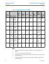
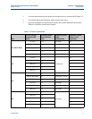
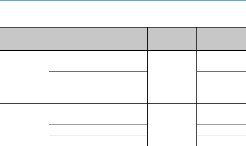
Table 1-3 Power requirements
Size
AC line voltage,
frequency and
phase
Hydraulic system
motor full load
amps
Hydraulic system
motor
configuration
Hydraulic control
valve in-rush
amperage