


Operating and maintenance instructions Section 4: Maintenance
3-9008-701 Rev J January 2015
Measurement Piston and Flow Tube 53
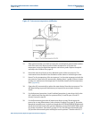
1. Disassemble the optical and hydraulic systems following the appropriate disassembly
instructions. See Section 4.4.2 and Section 4.4.3 respectively.
2. Slide a piece of plastic tubing, approximately 2 feet longer than the flow tube, over the
actuator shaft and remove the optical detector shaft from the threaded mounting
boss.
3. Attach the outlet flange to a hoist and support the flange so that it will be held in place
when the tie rods are removed.
4. Make sure that the support saddles below the flow tube will hold it in position without
allowing it to drop when the outlet flange is removed. Adjust if necessary.
5. Remove the tie rod nuts securing the outlet flange assembly.
6. Remove the outlet flange.
7. Use the tube protecting the actuator rod to push the measurement piston to the end of
the flow tube. DO NOT PUSH THE MEASUREMENT PISTON OUT OF THE FLOW TUBE.
8. Using sufficient personnel (at least 2), pull the measurement piston out of the flow
tube. Be sure to support the weight of the piston as it is removed from the flow tube.
This will keep the actuator shaft from damaging the flow tube.
9. After removal, support the piston in such a way as to prevent the piston weight from
resting on the seals on the front of the measurement piston.
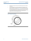
10. Press the poppet valve open and secure it in position using a wooden block or non-
marring dowel.
11. Remove the o-ring from the groove in the poppet valve. Removal of the poppet valve at
this time will ease replacement of the poppet seal.
12. Remove the piston seals and rulon riders.
13. Carefully clean and examine the flow tube bore for scoring, corrosion or other signs of
wear or damage. Consult the factory concerning replacement.
14. Remove the tie rods from the prover excluding the two tie rods at the bottom. These
may remain in place.
15. Lift the flow tube slightly off the support saddles. Pull it away from engagement with
the inlet flange. A hoist will be necessary for this operation.
16. Remove the inlet and outlet flange o-rings and inspect for damage.
Procedure A: Piston and Flow Tube Assembly
In the following procedure where lubrication of parts is recommended, it should be noted that
excessive amounts of lubrication should be avoided as the base volume of subsequent water
draw could be affected.
1. If the upstream flow tube o-ring is to be replaced, install the new o-ring in its groove
using lubricant (white lithium grease) to hold in place.
2. Install the flow tube on its saddles, flush against the inlet flange. Adjustment of the
saddles may be necessary.