


Operating and maintenance instructions Section 4: Maintenance
3-9008-701 Rev J January 2015
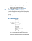
Measurement Piston and Flow Tube 59
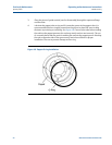
5. Test fit of the rulon riders on the measurement piston. Trim any excess length so that
there will be a 1/16” (2 mm) gap between the ends of each rider. Remove the riders
from the piston and lay them aside for later use.
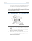
Important:
The 12” compact prover has two different sized riders; a thick rider and a thin rider. The thick
rider fits in the upstream groove of the piston. The thin rider fits in the downstream groove of
the piston, between the two piston seals. All other size provers have identical riders.
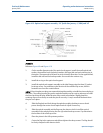
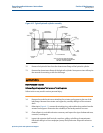
6. Lubricate the inside of the flow tube with light oil. Align the flow tube with the
measurement piston.
7. Carefully slide the flow tube over the measurement piston until the first seal goes into
the flow tube. Take care to prevent the seal from folding backwards during this process.
Install the first rulon rider onto the measurement piston with the gap at the bottom of
the piston. Lubricate the rider with light oil.
8. Slide the flow tube over measurement piston up to the rear rider. The second piston
seal should slip into the flow tube without fail.
9. Install the second rulon rider onto the measurement piston with the gap at the bottom
of the piston. Lubricate the rider with light oil.
10. Press the flow tube over the measurement piston until the second rulon rider goes into
the flow tube.
11. Slide the flow tube up to the upstream flange.
12. Install the o-ring in the groove of the outlet flange using lubricant to hold it in place.
13. Lift the outlet flange with a hoist and align it on the end of the flow tube. Insert four (4)
tie rods through the flow tube flanges that are diagonal from each other.
14. Install the tie rod nuts to the four tie rods and tighten them to pull the flow tube and
the outlet flange snug against the inlet flange. Pay attention to the o-rings in the end
flanges and be certain they remain in place. Care should be taken to avoid scraping
paint into the space between the flanges and the flow tube.
15. Install the remaining tie rods and nuts. Tighten nuts enough to bring the flanges and
flow tube together.
16. Check the alignment of the outlet flange with the inlet pipe flange. A standard level and
the installation studs (for the outlet flange) may be useful. Rotation of the outlet flange
will bring the bolt pattern into alignment.