


Operating and maintenance instructions Section 3: Operation
3-9008-701 Rev J January 2015
Operating instructions 33
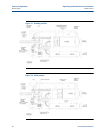
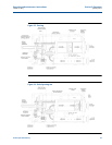
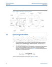
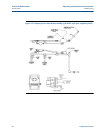
Figure 3-7 Hydraulic system
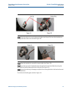
7. Vent all air from the system using the hand valves located on the inlet and outlet flanges
of the flow tube. Slowly close the process fluid diverter valve (double block and bleed)
and open the outlet valve. The prover is now ready to begin the proving cycle.
8. Connect the signal cable from the meter under test to the operating computer for
proving operations. Once the operating computer receives all the signals, proving runs
can begin. Reference the operating computer instruction manual for proper computer
operation.
9. After proving runs are completed and results are satisfactory, the process flow may be
diverted back to the process line as described in steps 10 and 11. Once this is done,
power down the prover.