


Operating and maintenance instructions Section 4: Maintenance
3-9008-701 Rev J January 2015
Base volume determination 37
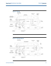
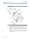
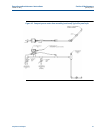
5. Place the measurement piston in the upstream position for simple attachment of the
indicator rod. The measurement piston may be moved upstream by activating the
hydraulic system.
6. The indicator rod is designed in multiple sections to span a distance that will reach the
length of the optical assembly. This allows for multiple leak check positions along the
flow tube. The first rod piece to be used is the piece with the larger thread. Insert this
piece through the hole in the support stud and thread into the end of the detector
shaft. Add rod sections as necessary to reach leak check positions desired, pay
attention to the area between the volume switches. The measurement piston can be
moved downstream by releasing pressure on the outlet flange vent valve.
Important:
Do not allow indicator rod to completely go into the support stud while moving the
measurement piston downstream. Allowing the indicator rod to go completely into the support
stud may result in severe damage to the equipment
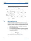
7. Be certain the hydraulic system motor is not running before the leak check test begins.
This assures that only the spring plenum pressure is acting on the measurement piston.
8. Position the dial indicator probe near the indicator rod. Slide the screw collar down the
indicator rod until contact is made with the probe of the dial indicator. Move the screw
collar only slightly more in order to ‘pre-load’ the dial indicator and then tighten the
collar to the indicator rod.
9. Zero the dial indicator and monitor for five minutes. A dial indicator movement greater
than 0.004 inches (.102 mm) in five minutes indicates that a leak is present in the
system. Inspect the system and eliminate any leaks. Remove any possible trapped air.
Refer to Section 5: Troubleshooting for detailed instructions on measurement piston
seal replacement if necessary.
10. Once testing is complete and results are satisfactory, return the measurement piston to
the full upstream position and remove all parts of the indicator rod and the remaining
components of the seal leak detector kit from the prover and replace the screws in the
support stud and mounting boss.
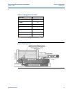
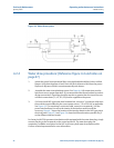
4.2 Base volume determination
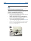
4.2.1 Certification techniques
Compact prover base volume determination varies with frequency of use and operating
environment. Annual base volume re-certification is typical. Re-certification cycles should not
exceed three (3) years. The volume determination procedures in this manual are designed to
assist the user in creating an effective certification program.
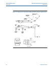
The exact upstream and downstream base volumes must be known for correct proving
calculations. For example, a 12” compact prover with a nominal volume of 15 U.S. gallons could