


Operating and maintenance instructions Section 4: Maintenance
3-9008-701 Rev J January 2015
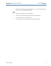
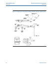
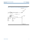
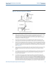
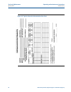
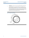
Water draw procedure: (Reference Figure 4-4 and notes on page 47) 47
level in the test measure near the zero mark. When the flag enters the first optical
volume switch, the solenoid valve (SV) will close.
31. Fully open valve W3 to drain the test measure and wait any specified drain time. Close
valve W3. At this point, actuating the RUN/RETURN switch (S1) will begin the next
measurement cycle. (See Note 3 on page 47.) The procedure may now be repeated
from step 12 for as many Combined water draw cycles as desired. See Note 2 on page
47.
Notes for water draw procedures:
1. Once the water draw displacement procedure is started it should be carried to
conclusion in a continuous process without interruption or delay.
2. One measurement cycle of the water draw process must be performed with the flow
rate reduced 25 to 50%. This may be accomplished by throttling valve W1. This is
typically performed for the second cycle.
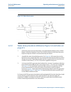
3. Run/Return and Upstream/Downstream selector switches are labeled S1 and S2
(respectively) on the Interface Board itself. ATEX style provers, and NEC provers
equipped with the optional water draw plug, have these switches operational to the
front of the control enclosure, or interface enclosure (as applicable). Labels on the front
of the enclosure will dictate the switch operation for water draw purposes.
4. The optical cover should be replaced for each measurement cycle. However, it does not
have to be fastened permanently each time. Simply slip the cover completely over the
optical assembly to black out any ambient light that could alter optical switch
operation.
5. Once the water draw procedure is completed, replace the optical cover and follow the
procedure in Section 2.4.