


Operating and maintenance instructions Section 1: Introduction
3-9008-701 Rev J January 2015
Technical data 9
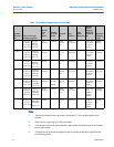
5. For more information on pulse quality and compact provers, reference API Chapter 4.2.
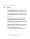
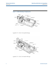
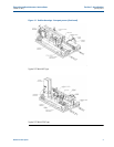
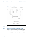
6. For certified dimensional drawings, please contact the factory.
7. Upstream multipliers are approximate. Actual values can be obtained from the Base
Volume Certification (water draw) method.
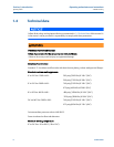
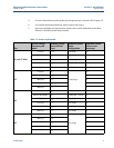
Table 1-3 Power requirements
Size
AC line voltage,
frequency and
phase
Hydraulic system
motor full load
amps
Hydraulic system
motor
configuration
Hydraulic control
valve in-rush
amperage
8” and 12” Mini
115/60/1
13.4
1Hp Single 10
220/50/1 &230/60/1
6.7
1 Hp Single 5
380/50/3
3.0
1.5 Hp Single .2
415/50/3
2.7
1.5 Hp Single .2
460/60/3
2.2
1.5 Hp Single 5
12”
115/60/1
19
1.5 Hp Single
10
220/50/1 & 230/60/1
8.4
5
380/50/3
3.0
.2
415/50/3
2.7
.2
460/60/3
2.2
5
18”
115/60/1
19
1.5 Hp Dual, 2 Circuits .2
220/50/1 & 230/60/1
19
1.5 Hp Dual, 1 Circuit .2
380/50/3
9.4
5 Hp Single .2
415/50/3
8.2
5 Hp Single .2
460/60/3
6.5
5 Hp Single .2
690/50/3
4.8
5 Hp Single .2
24”
230/60/3
13
5 Hp Single
.2
380/50/3
9.4
.2
415/50/3
8.2
.2
460/60/3
6.5
.2
690/50/3
4.8
.2