


Operating and maintenance instructions Section 4: Maintenance
3-9008-701 Rev J January 2015
Measurement Piston and Flow Tube 57
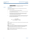
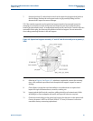
22. Follow the appropriate assembly procedures for installation of the hydraulic seal
support, hydraulic cylinder, optical seal support, and optical assembly. See Section 2.4,
Section 4.4.2 and Section 4.4.3.
23. It is recommended that the leak check procedure be performed after seal replacement
to assure that the measurement piston seals are working correctly. See Section 4.1.
24. A hydrostatic pressure test is also recommended following the re-assembly of the
Compact Prover.
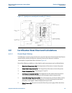
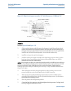
Procedure B: Piston and Flow Tube Disassembly
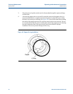
1. Place the measurement piston in the full upstream position. Close nitrogen valve.
2. Attach the outlet flange to a hoist and support the flange so that it will be held in place
when the tie rods are removed.
3. Make sure that the support saddles below the flow tube will hold it in position without
allowing it to drop when the outlet flange is removed. Adjust if necessary.
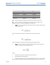
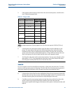
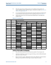
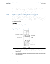
Table 4-2 Tie rod nut torque
Prover size Nut size
Torque requirement
150 300 600
Ft - lbs N - m Ft - lbs N - m Ft - lbs N - m
8
3/4”
115
156
1”
153
208 396 537 396 537
12m
1”
159
216 412 559
1-3/8”
906 1230
12
1”
127
172 330 448
1-3/8”
906 1230
18
1-1/4
389
528 1008 1368
1-1/4”
1612 2188
24
1-1/4”
807
1095
1-1/2”
646
877 1675 2273
1-5/8”
3734 5067
1-7/8”
3140 4261
34
2”
1521
2064 3945 5353 n/a n/a
40
2”
4168 5656 n/a n/a