


30 Operating instructions
Section 3: Operation Operating and maintenance instructions
January 2015 3-9008-701 Rev J
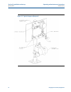
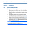
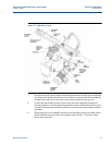
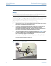
Figure 3-5 Piston returning to upstream position
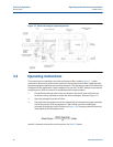
3.2 Operating instructions
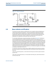
The compact prover should be connected to the process line, similar to Figure 2-1, either
upstream or downstream of the meter under test. Electrical power should be supplied and the
operating computer should be connected to the prover. The operating computer should also be
configured for the application. If these conditions are not met, DO NOT attempt to operate the
compact prover. Refer to Section 2 for Installation and Set-up procedures.
1. Check all drain and vent valves to be sure that they are closed. Vents and drains are
located on the top and bottom of the flow tube end flanges. Reference Figure 1-2.
2. Open the spring plenum shut-off valve.
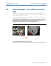
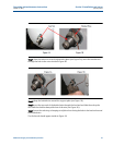
3. The pneumatic spring plenum must be charged with dry nitrogen for proper operation.
Check the pressure in the spring plenum. There will be a factory-installed gage
mounted to the plenum tank for reference (Figure 3-6). The proper plenum pressure is
determined by the following formula:
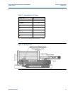
where R is a known constant for each size prover. See Table 3-1 below.