


Operating and maintenance instructions Section 4: Maintenance
3-9008-701 Rev J January 2015
Optical Seal Support 61
7. Remove the three (3) socket head screws from the optical seal support that hold it to
the inlet flange. Remove the seal support and o-ring by carefully sliding it off the
detector shaft. Inspect for wear or damage.
TIP: If the conduit connection to the optical seal support needs to be removed, loosen the
clamping nut on the blue conduit and remove the connection pins from inside the wiring
harness plug described in step 3. A small pointed utensil may be used for this. Once the wires are
removed from the plug, the wires may be pulled out of the seal support. Do not remove the
clear tubing protecting the wires in the seal support.
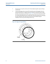
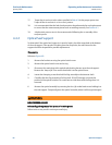
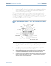
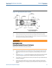
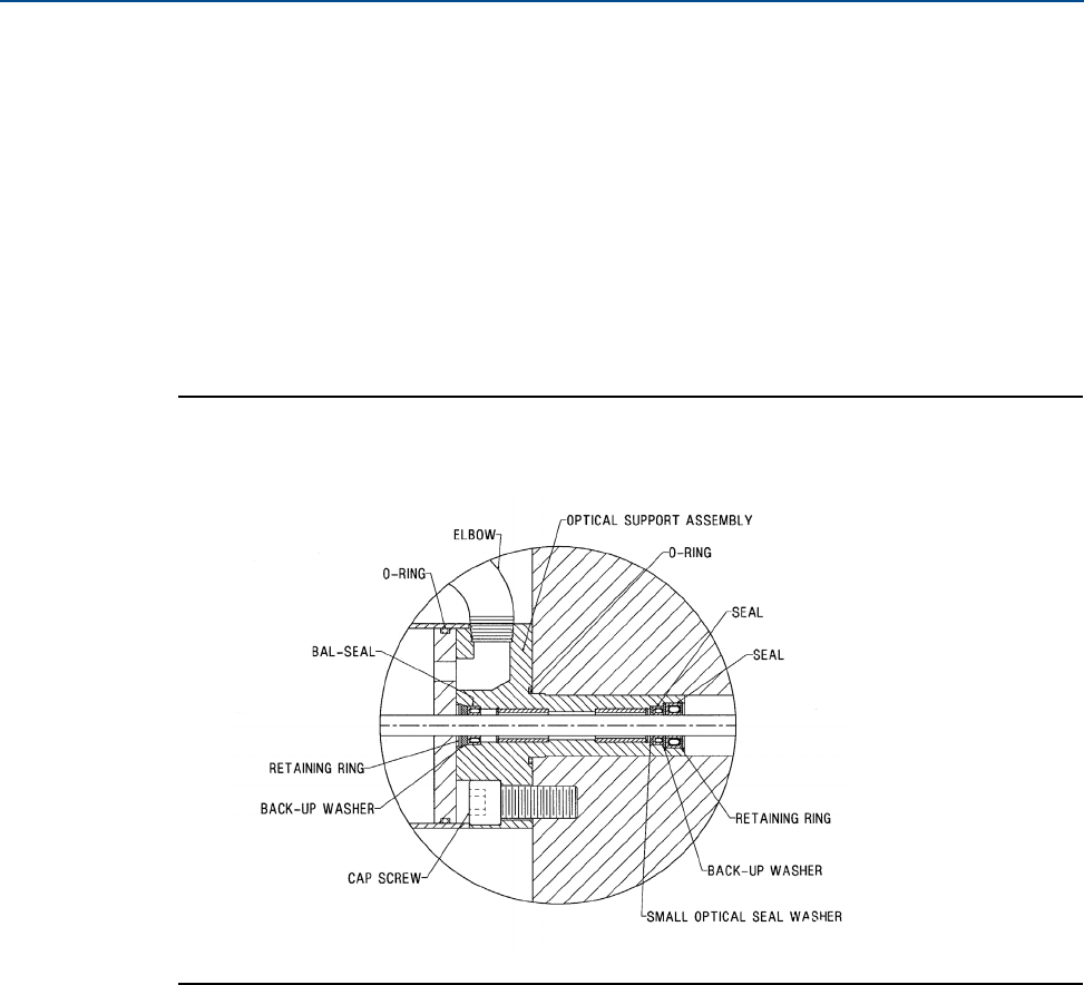
Figure 4-9 Optical seal support assembly - 8” and 18” and all units built prior to January 1,
2006
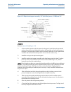
8. Referring to Figure 4-9 or Figure 4-10, whichever is applicable, remove the retaining
rings, seals, and back-up washers from the optical seal support. Inspect for wear or
damage.
9. Clean all parts (except electrical assemblies) in a suitable solvent as required and
inspect for signs of abnormal wear, corrosion, cracking, etc.
10. Inspect optical shaft for nicks, scratches, galling or build up of contaminants. Polish
with 400 grit or finer sandpaper with water and wipe with solvent as required.
11. Check the rulon bushings in the optical seal support for clearance on the optical shaft.
Correct clearance is .0015 to .005 inch (.038 to .127 mm). If clearance is excessive
consult the factory concerning replacement.