


Operating and maintenance instructions Section 4: Maintenance
3-9008-701 Rev J January 2015
Hydraulic Cylinder and Hydraulic Seal Support 65
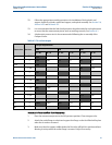
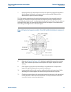
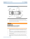
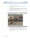
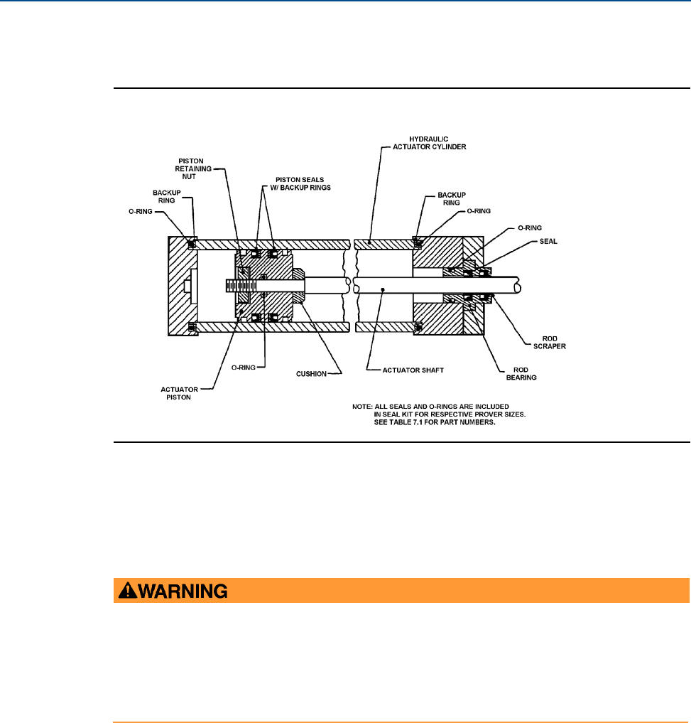
Figure 4-12 Typical hydraulic cylinder assembly
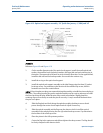
12. Remove the hydraulic lines from the downstream flange of the hydraulic cylinder.
13. Remove the downstream flange of the hydraulic cylinder. Some prover sizes will require
the removal of mounting screws for this flange.
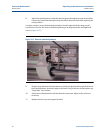
14. Remove the socket head screws attaching the actuator seal support to the tee of the
inlet flange. Remove the actuator seal support by carefully sliding it off the actuator
shaft.
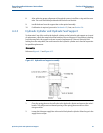
15. Referring to Figure 4-11, remove the retaining ring, seals and back-up washer from the
actuator seal support. Determine the suitability of the backup washer for reuse.
16. Clean all parts in a suitable solvent as necessary and inspect for signs of abnormal wear,
corrosion, cracking etc.
17. Inspect the actuator shaft for nicks, scratches, galling, or build up of contaminants.
Polish with 400 grit or finer sandpaper (emory cloth) and water. Wipe with solvent as
needed.
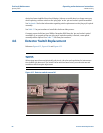
HIGH PRESSURE HAZARD
Release all pipeline/process fluid pressure from the prover.
Failure to do so may result in serious personal injury.