


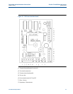
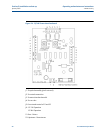

16 Connection of the operating computer
Section 2: Installation and set-up Operating and maintenance instructions
January 2015 3-9008-701 Rev J
the motor starting switch will be necessary for this conversion. Be sure to follow all applicable
electrical codes for the area of installation.
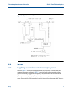
2.2.2 Connection of the operating computer
Standard provers are shipped with a control cable for connection to the operating computer. If
an electrical conduit connection is desired, remove the existing control cable. Access to the
interface enclosure will be necessary for this conversion. Be sure to follow all applicable
electrical codes for the area of installation.
The compact prover control signals are designed to worldwide control standards. This includes
digital and analog signals. The electrical schematic will define how each connection (conductor)
is used. Manuals and instructions supplied with the operational computer of choice will assist
with proper control connections. Reference Section 5.2 for additional troubleshooting
information. If you require further assistance for these connections, contact a local Daniel repre-
sentative.
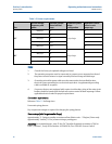
The operating computer will need to be properly configured for the application and must be
capable of Dual Chronometry Pulse Interpolation
. This calculation method requires the
computer to have a high frequency master oscillator, which counts time in 0.000001 parts of a
second.
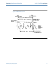
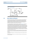
This master oscillator must operate two counters, referred to here as “Time A” and “Time B”.
Time “A" must start counting when the flag trips the first detector switch. Time “B” must start
counting with the leading edge of the first flowmeter pulse after Time A has started.
Time “A” is stopped when the flag trips the final detector switch. Time “B” is stopped with the
leading edge of the first flowmeter pulse after Time “A” has stopped, (Reference Figure. 2-2).
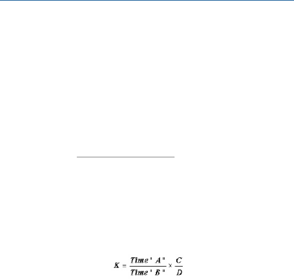
Using the ratio of Counter Time “A” and Counter Time “B” will allow for accurately counting a
fraction of a flowmeter pulse to within 1 part in 10,000 as shown below:
K= K-Factor, or counts per unit volume, from the flowmeter
A = Time for displaced volume B = Time for whole meter pulses
C = Total number of whole meter pulses
D = Displaced volume
Qualified personnel who are knowledgeable of the computer’s operating system, configuration
variables, and compact proving applications should complete the configuration of the
operating computer.