Operating and maintenance instructions Section 5: Troubleshooting
3-9008-701 Rev J January 2015
Measurement Piston Movement 75
5.3 Measurement Piston Movement
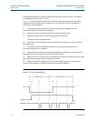
Piston does not move upstream: (No hydraulic pressure)
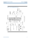
1. Check to be sure the hydraulic system motor is running. If so, check the hydraulic
control valve operation by disconnecting the AC voltage at the junction box adjacent to
the valve. If the Piston fails to return, the hydraulic control valve is stuck open and is in
need of repair or the hydraulic pump is defective.
2. If the piston returned in step 1, reconnect the AC voltage to the control valve and then
unplug the DC power to the control relay at connection J-4 on the prover interface
board. If the piston does not return, the control valve relay is defective.
3. If the piston returned in step 2, check the voltage between pins 2 (-) and 5 (+) of
connection J-2 on the interface board. If this voltage is low (less than 2V), the operating
computer is responsible. If this voltage is high (more than 8V), the interface board is
defective.
4. If the operating computer is found responsible, check the red LED on the prover
interface board. If this LED is illuminated, and the flag is not in a volume switch, this
indicates a problem in the volume switch circuit. Make a jumper connection between
pins 2 and 3 of connection J-1 on the prover interface board. If connecting this jumper
turns the LED off, check the optical barriers for approximately 230 ohms resistance (for
fuse barriers, 250 ohms for non-fused) across connection terminals 1 and 3. If no
resistance is detected, replace the fuse of the barrier in question (or replace the non-
fused barrier) and check the grounding system integrity.
If the barrier resistance is found acceptable, the cause will be in the optical assembly wiring or
volume switches.
Piston does not move downstream: (Hydraulic pressure will not release)
1. Apply the correct AC voltage for the solenoid at the connection to the hydraulic control
valve. If the control valve fails to open (piston does not launch), the solenoid may be
defective or the valve itself is stuck closed.
2. If the control valve opened in step 1, disconnect J-4 on the prover interface card and
apply a voltage of 12VDC to the control side of the relay. If the control valve does not
open, the control valve relay is defective.
3. If the control valve opened in step 2, reconnect J-4 and jump a connection between pins
2 and 5 of J-2 on the prover interface board (control voltage must be present at pin 4 (+)
and 2 (-) of J-2).
If the control valve does not open (piston does not launch), the prover interface board is
defective.
4. If the control valve opened in step 3, the operating computer is not sending the run
command (dropping to 0V) to pin 5 of J-2. One possible cause for this problem may be
that the operating computer is not receiving the upstream signal from the optical
assembly. The voltage between pins 6 (+) and 2 (-) of J-2 on the prover interface board
should be low (less than 2V) and the green LED illuminated (if equipped) with the piston


