


Operating and maintenance instructions Section 4: Maintenance
3-9008-701 Rev J January 2015
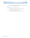
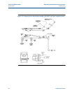
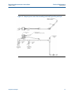
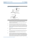
Water draw procedure: (Reference Figure 4-4 and notes on page 47) 43
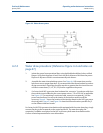
4. Supply appropriate operational voltage (+12 or 24 VDC) to the prover interface board
at receptacle J-2, pins 2 (-) and 4 (+). Reference Section 2.4 to verify proper voltage
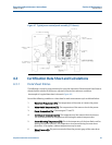
required for the interface board. Reference Figure 2-3 and Figure 2-4 for the location of
J-2.
5. Loosen and remove the cover on the optical detector switch assembly. Be careful not to
damage the optical switches on removal or replacement of optical cover during the
entire water draw process. See Note 4 on page 47.
6. Be sure the prover hydraulic system is connected to the appropriate AC power source.
Reference the documentation package for the electrical schematic to verify proper
voltage required.
Do not start the hydraulic system motor at this time. Check to see that the hydraulic tank is
filled to its proper level, reference Section 3.2, step 4.
7. Verify the spring plenum cut off valve is open and adjust the spring plenum pressure to
approximately 75 psig (5.3 kg/cm ).
8. The prover and water draw system must now be filled with water and cycled to purge
ALL air. See Note 1 on page 47.
Open valves V1, V2, D1, D2, W1 and W3. Start the flow of water into the prover. As the prover
fills with water, air will escape through valve W1. Observe the flag position.
The measurement piston will travel to the full downstream position. Once water appears at W1,
set the valves for upstream flow by closing V2 and D1. Valves V1, D2, W1 and W3 remain open.
Observe the flag position.
The measurement piston will now travel to the full upstream position. When water appears
again at W1, reset the valves for downstream flow by opening D1 and V2, and then closing V1
and D2. After the piston reaches the full downstream position, this process should be repeated
until ALL air is removed from the system.
9. Once all the air is removed, set the valves for downstream flow (first open V2 and D1,
then close V1 and D2). Close valve W3 to allow the test measure to begin filling. When
the test measure fills, throttle valve W3 to allow water to escape at the same rate that
water is entering the test measure to maintain the water level in the test measure at or
near the zero mark. Allow system to circulate until the prover and test measure
temperatures are within 1/2.F (1/4.C) of each other.