


Operating and maintenance instructions Section 2: Installation and set-up
3-9008-701 Rev J January 2015
Installation 13
21TOP (14)
Section 2: Installation and set-up
2.1 Installation
The compact prover may be installed permanently in a process line or used as a portable unit.
The prover is intended for above ground use and should be operated level to prevent the
formation of air pockets within the flow tube. A permanently installed standard prover should
be set up horizontally with considerations given to the accessibility of electrical power and
control operation. Consult a Daniel representative for further information regarding portable
provers.
Important
For optional vertical installation, special modifications to the prover hydraulic system and flow
tube supports will be required. The standard prover built for horizontal installation should not
be installed in a vertical position without proper modifications.
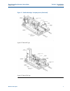
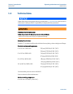
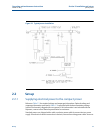
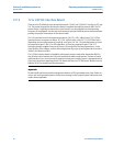
Refer to Figure 2-1 for a typical, permanent, compact prover installation in a process line.
Installation of a double block and bleed valve configuration is recommended in the process line
to assure that all metered fluid is passing through the prover. Be sure to follow API guidelines for
ANSI flanged connections and proper locating distance from the meter under test. Use gaskets
and retaining bolts of proper size and pressure rating for prover inlet and outlet flanges.
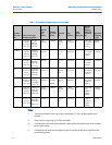
ReferenceTable 1-2 for correct flange information. Consideration of available workspace around
the prover is necessary for normal operation and maintenance.
When installing this equipment, bolting must conform to the requirements of ASME B16.5
paragraph 5.3 and to the material requirements of ASME B16.5 Table 1B. Gaskets must conform
to the requirements of ASME B16.20.
It is the customer's responsibility to ensure that piping or other attachments connected to the
compact prover do not place adverse stresses on the compact prover. The design of the
compact prover has not been assessed for the effects of traffic, wind or earthquake loading.
It is the customer's responsibility to provide fire prevention measures and equipment per local
regulations.
The compact prover has been designed with a minimum of 1.5mm (1/16 inch) corrosion
allowance. The customer should implement a periodic inspection and maintenance program to
ensure that no part of the compact prover's pressure-retaining components has corrosion or
erosion exceeding this amount.