


36 Seal Leak Check
Section 4: Maintenance Operating and maintenance instructions
January 2015 3-9008-701 Rev J
Important:
It is ESSENTIAL that the liquid and prover temperatures remain stable during the leak check
procedure as thermal expansion or contraction will give incorrect results.
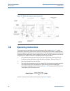
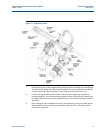
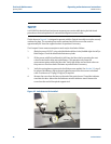
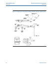
The kit shown in Figure 4-1 is designed to operate with the Optical Assembly cover tube securely
anchored in place. The mounting boss on the outboard end of the cover tube must be
approximately 90° from the support bracket. Re-position if necessary.
The Compact Prover measurement piston seals may be checked as follows:
1. Block the prover OUTLET using a double block and bleed valve (bubble-tight shut off) or
blind flanges. Check the block and eliminate any leaks.
2. Fill the prover with fluid and bleed ALL AIR from the flow tube by operating the vent
valves located on the inlet and outlet flanges. This operation may move the
measurement piston within the flow tube. Verify that all the vent and drain valves on
the prover are free from leaks. Eliminate any and all leaks if necessary.
3. Verify the spring plenum pressure for the fluid pressure applied. See Section 3.2, step 3,
for proper calculations. Adjust the spring plenum pressure to the correct calculated
value. A minimum of 75 psig (5.3 kg/cm) is required.
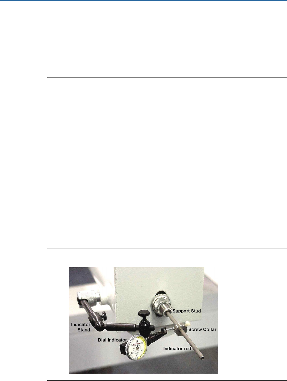
4. Remove the screw from the boss on the end of the optical cover. Thread the indicator
stand into the boss. Mount the dial indicator onto the indicator stand. Remove the
screw from the end of the optical support stud.
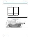
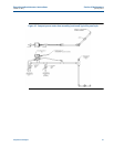
Figure 4-2 Leak detector kit installed