


Operating and maintenance instructions Section 3: Operation
3-9008-701 Rev J January 2015
General operational theory 27
Section 3: Operation
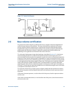
3.1 General operational theory
The operational sequence of the compact prover is as follows:
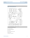
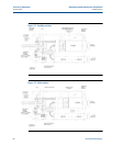
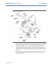
1. The measurement piston is normally in the upstream (standby) position, with the
poppet valve open, and is held in place by the hydraulic pressure on the actuator piston
(Figure 3-1).
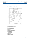
2. The hydraulic control valve opens and releases the hydraulic pressure. Pressure from
the pneumatic spring plenum, on the upstream side of the actuator piston, closes the
poppet valve and the piston begins moving downstream at the process fluid flow rate
(Figure 3-2).
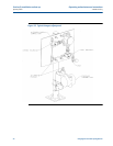
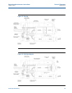
3. As the measurement piston moves downstream, the optical volume switches are
‘tripped’ by the flag connected to the piston (Figure 3-3). These volume switch signals
are instantly sent to the operating computer for calculations discussed in Section 4.6.
4. When the flag trips the second optical volume switch, the hydraulic control valve closes.
Hydraulic pressure builds and begins to push the actuator piston upstream, opening
the poppet valve. Process fluid is then allowed to flow through the piston (Figure 3-4).
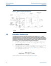
5. The actuator piston, measurement piston, poppet, actuator shaft, detector shaft and
flag will then move back to the upstream (standby) position (Figure 3-5). Once the
upstream position is reached (Figure 3-1), the hydraulic pump will assume it’s neutral
condition maintaining hydraulic pressure to hold the measurement piston upstream.
The prover is now ready to begin another pass.
A positive stop feature is incorporated into the outlet flange for fail safe operation. This prevents
any accidental blockage of the process flow stream. Reference Figure 3-4.