


80 The auto plenum adjust panel
Section 5: Troubleshooting Operating and maintenance instructions
January 2015 3-9008-701 Rev J
5.4 The auto plenum adjust panel
Compact prover plenum adjustment panels can have either AC or DC power solenoids.
Sometimes these solenoids will not work correctly or at all. The problem typically lies in the
control circuits for the solenoid relays. These circuits for the relays are DC powered directly from
the operating computer. The control coil of these relays must be wired to match the computer
output configuration.
Signal determination:
Prover flow computers use one of the following output signal types for charge and vent:
• Driving current
• Sinking current
Note
• Measure the signal voltage levels at TB1 wit a typical DMM (Digital multi meter) set for DC
voltage in the prover interface closure or at the relay itself. TB1 is the most common place
to take these measurements because all conductors and signals should be present.
• If the signal does not change state (with high or low voltage) at TB! or at the relay, trace
back to the operating computer for accurate measurements. There should be no loose or
corroded connections.
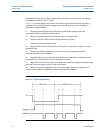
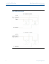
Driving current signal
The operating computer will output a +24V DC signal when active and the DC negative will be
common to both relays. When not active, the signal will go to 0V DC.
• Use a negative reference (-) for the DMM at a convenient point where the computer and
prover DC negative is common between two.
• If necessary, disconnect the signal conductor at the computer to take accurate
measurements.
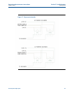
Sinking current signal
The operating computer will output a DC negative signal when active and the +24V DC will be
common to both relays. When not active, the signal will go to +24V DC.
• Use a positive reference (+) for the DMM at the main DC power source for the system or at
TB1.
• If necessary, disconnect the signal conductor at the computer to take accurate
measurements.