


58 Measurement Piston and Flow Tube
Section 4: Maintenance Operating and maintenance instructions
January 2015 3-9008-701 Rev J
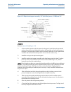
4. Remove the tie rod nuts securing the outlet flange assembly.
5. Remove the outlet flange and then all but the lower two tie rods.
6. Using a hoist, support the flow tube. Take care to keep the flow tube level to prevent
damage to the piston, actuator shaft, and detector shaft.
7. Keeping the flow tube level, slide the flow tube off the piston.
8. After removal, support the piston in such a way as to prevent the piston weight from
resting on the seals of the hydraulic seal support or the optical seal support.
9. Press the poppet valve open and secure it in position using a wooden block or non-
marring dowel.
10. Remove the o-ring from the groove in the poppet valve. Removal of the poppet valve at
this time will ease replacement of the poppet seal.
11. Remove the piston seals and rulon riders.
12. Carefully clean and examine the flow tube bore for scoring, corrosion or other signs of
wear or damage. Consult the factory concerning replacement.
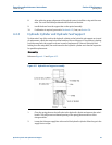
Procedure B: Piston and Flow Tube Assembly
1. In the following procedures where lubrication of parts is recommended, it should be
noted that excessive amounts of lubrication should be avoided as the base volume of
subsequent water draw could be affected.
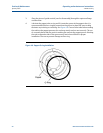
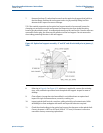
2. Lubricate the poppet valve o-ring and fit it onto the groove in the poppet valve. It is
recommended that the o-ring be pressed into the groove in places 90° apart to help
eliminate any twisting or stretching. See Figure 4-8. Care must be taken when working
the seal into the poppet groove as the seal may stretch and not seat correctly. The use
of a smooth plastic tool may assist in working the seal into the poppet groove. Working
the seal on opposite sides of the groove every few inches will assist in proper
installation. Use care to prevent damage to the o-ring.
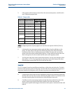
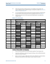
3. If the poppet valve has been removed from the measurement piston, install it at this
time. See Table 4-1 for torque values.
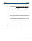
4. Lubricate the two measurement piston seals with light oil and install them on the
piston. The open sides of the two seals will be facing away from each other when
installed correctly. Each seal will require proper fitting. Once the seal is around the
groove, the seal must be pushed into the groove. A ‘snap’ will be heard once the seal
seats in the groove. Be sure to check that the entire seal is properly seated.