


62 Optical Seal Support
Section 4: Maintenance Operating and maintenance instructions
January 2015 3-9008-701 Rev J
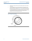
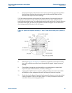
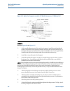
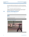
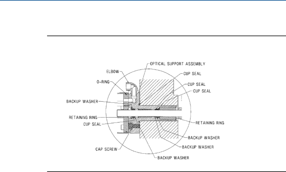
Figure 4-10 Optical seal support assembly - 24” (built after January 1, 2006) and 34”
Assembly
Reference Figure 4-9 and Figure 4-10
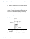
1. On the smaller diameter end of the optical seal support, install the small optical seal
washer, the small bal-seal, the backup washer, the larger bal-seal and retaining ring in
that order. The open ends of all seals are to face into the flow tube. On the opposite end,
install the bal-seal and the backup washer. Secure with the retainer ring.
2. Install the o-ring on the optical seal support.
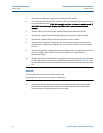
3. Install the optical seal support assembly to the inlet flange using the three (3) socket
head cap screws. Pay attention to the location of the modified cap screw, which is
located across from the conduit elbow.
NOTE: If the wiring harness plug was removed during disassembly, reinstall the wires and plug at
this point. The mating harness plug on the optical assembly may be used as reference to install
the wires back into the plug. Make the wire colors match one another. Slightly bend the
retaining clip out if necessary to make the pins fit securely. A ‘snap’ sound will be heard when
the pins are in place.
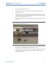
4. Slide the flag back and forth along the optical assembly checking to assure that it
passes through the center of each optical switch. Adjust if necessary.
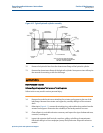
5. Slide the optical assembly and the flag over the detector shaft. Install the optical
assembly to the seal gland using the four (4) socket head cap screws. Pay attention to
the location of the small cap screw.
6. Place the piston in the full upstream position.
7. Center the flag in the upstream switch then tighten the clamp screws. The flag should
be firmly clamped to the detector shaft.