


42 Water draw procedure: (Reference Figure 4-4 and notes on page 47)
Section 4: Maintenance Operating and maintenance instructions
January 2015 3-9008-701 Rev J
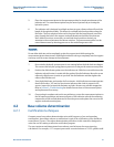
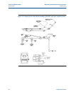
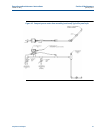
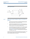
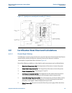
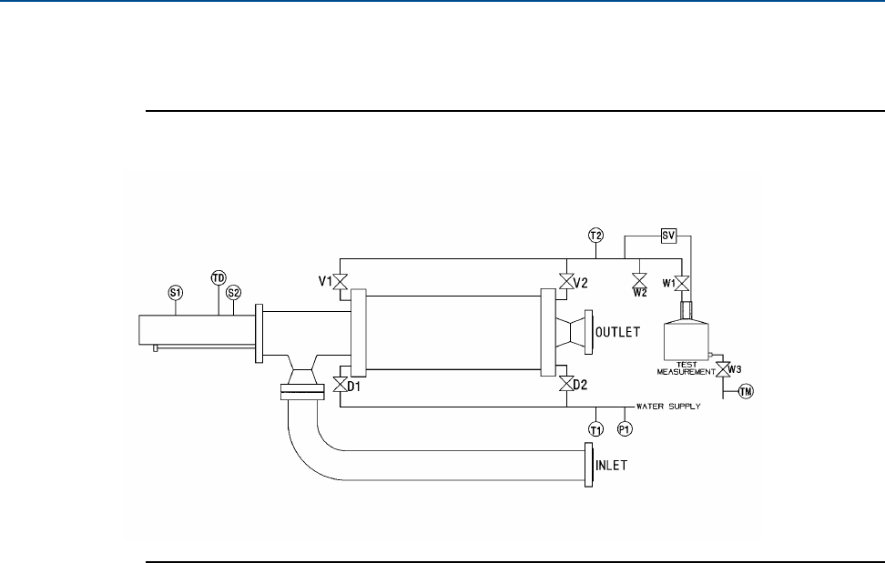
Figure 4-4 Water draw system
4.2.2 Water draw procedure: (Reference Figure 4-4 and notes on
page 47)
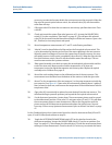
1. Isolate the prover from operational lines using double block and bleed valves or blind
flanges. Verify that the prover is level. Drain and flush all process fluid from the prover.
Dispose of all process fluids in an environmentally safe manner.
2. Assemble the water draw plumbing system. See Figure 4-4. All connections must be
leak-free to assure proper operation. It is recommended that thread sealant be used on
all pipe connections. Pipe sizing should be equal to or greater than the size of the vent
and drain connections (V1, V2, D1, D2) that are supplied on the prover.
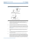
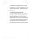
3. For factory built NEC type water draw hardware kits, connect a 3 conductor cable from
the enclosure terminal block to the correct power source, 115 or 230 VAC as applicable.
See Figure 4-3. The remaining 2 conductor cable, connects to receptacle J-3 on the
prover Interface Board. Access to the interior of the interface enclosure will be
necessary. Figure 4-7 shows the location of the interface board on the NEC-type prover
electrical panel. Figure 2-3 and Figure 2-4 show the different locations possible for J-3
on the different interface boards.
For factory built ATEX type water draw hardware kits equipped with the water draw plug, simply
connect the plug to the receptacle on the control enclosure. The water draw plug and
receptacle is available as an option for the NEC style factory built water draw hardware kits.
Contact a Daniel representative for more information.