


Operating and maintenance instructions Section 1: Introduction
3-9008-701 Rev J January 2015
Mechanical description 3
the measurement piston by means of the detector shaft. The passage of the flag through the
slotted optical switches defines the displaced volume (base volume) of the prover. For detailed
information on the Optical Assembly, see Section 4: Maintenance.
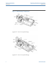
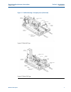
Hydraulic control valve:
This normally closed two-way valve controls the hydraulic operation of the prover. The valve is
energized to open during a proving pass, and de-energized to close for the piston return to the
upstream (standby) position. There are two styles of control valve used. Style is dependent
upon prover size and electrical system (NEC or ATEX Type). See Figure 1-1.
Hydraulic pump:
The hydraulic pump is a variable displacement vane-type unit driven by an electric motor. It
supplies the power necessary to overcome the plenum pressure and return the piston
upstream. Once the piston has reached the upstream position, the pump assumes a neutral
condition maintaining hydraulic pressure at no flow for minimum power consumption.
Pneumatic spring plenum:
The charge of pressurized gas in the pneumatic spring plenum supplies the energy necessary to
overcome the shaft seal friction and close the poppet valve. A portion of the charge is required
to overcome the force generated by the product pressure within the prover acting on the
actuator shaft and the detector shaft. When properly adjusted, this charge allows for minimum
pressure differential (usually only a few inches of water column) across the piston.