


Operating and maintenance instructions Section 4: Maintenance
3-9008-701 Rev J January 2015
Detector Switch Replacement 69
1. Disconnect electrical power to the unit.
2. Remove the support bracket at the outboard end of the detector shaft dust cover.
3. Remove the dust cover.
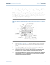
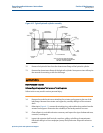
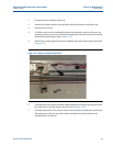
4. Carefully cut the wire ties holding the plug for the inoperative switch and remove any
‘hoop style’ anchors necessary. Disconnect the plug from the main harness by releasing
the latch and separating the plug. (Figure 4-13)
5. Remove the mounting/adjustment screws holding the optical switch to the switch pad.
(Figure 4-13)
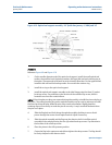
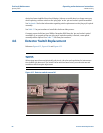
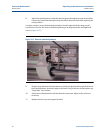
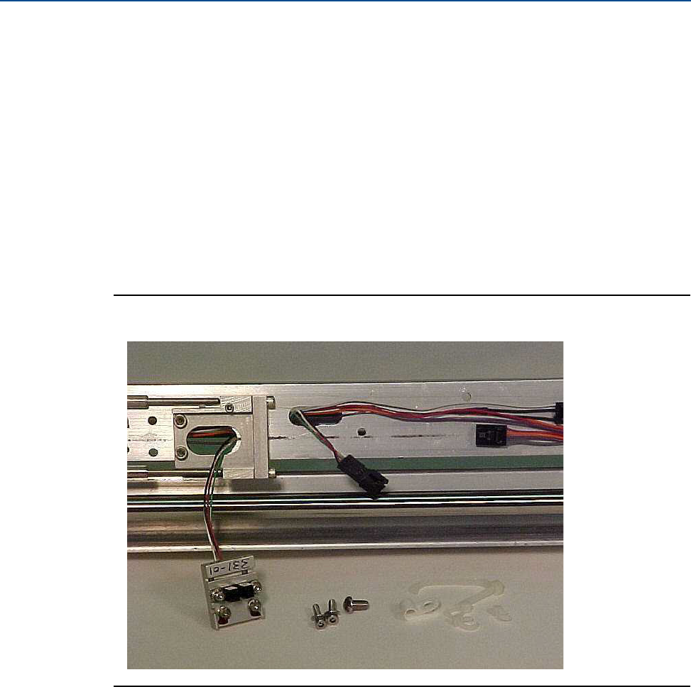
Figure 4-14 Detector switch removal #2
6. Carefully remove the switch assembly while feeding the switch plug through the frame.
Be careful not to catch the plug on any other wires. (Figure 4-14)
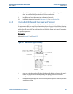
7. Install the new switch. For a volume switch, ensure that the assembly base is positioned
flat against the switch pad and square against the right end of the pad where the
elongated holes are located.