


2 Mechanical description
Section 1: Introduction Operating and maintenance instructions
January 2015 3-9008-701 Rev J
• Meter Factor: Correction factor (multiplier) for meter readout
1.3 Mechanical description
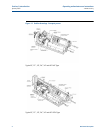
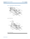
The basic outline of the compact prover and its component parts are shown in Figure 1-1. The
compact prover consists of a free flowing measurement piston and a coaxial mounted poppet
valve, all within a precision flow tube. The poppet valve is incorporated within the measurement
piston and is connected to the hydraulic cylinder by way of an actuator shaft. A calculated
pressure in the pneumatic spring plenum, in combination with the hydraulic system, operates
the actuator piston within the hydraulic cylinder. The pressure in the pneumatic spring plenum
closes the poppet valve, allowing the piston to proceed through a proving pass. Once the pass is
complete, the hydraulic system returns the piston to the upstream (standby) position while
holding the poppet valve open. Normal flow of the liquid will pass through the open poppet
valve. Optical sensors are used to detect the position of the piston inside the flow tube. These
sensors generate position signals, which are used for proper operation and data calculation.
Refer to Section 3: Operation for complete operation instructions.
Flow tube:
The flow tube is a stainless steel tube with a precision machined, hard chrome-plated bore. It
contains the prover piston, poppet valve, and fail-safe mechanism.
End connections:
The inlet and outlet end connections for installing the compact prover in line are ANSI 16.5
raised face flanges. Reference Section 1.4 for Technical data.
Hydraulic cylinder:
The hydraulic cylinder contains the actuator piston to act as a barrier between the gas in the
pneumatic spring plenum and the hydraulic oil. It provides the forces necessary to open and
close the poppet valve and to operate the prover through it’s cycle. Connected to the actuator
piston is the actuator shaft, which is connected to the poppet on the opposite end.
Optical assembly:
This intrinsically safe component is precision designed for accurate volume measurement within
5 ten thousandths (0.0005) of one inch or 0.0127 mm. There are three optical sensors
(switches) used: one for the upstream (standby) position, and two for defining the displaced
volume of fluid flowing through the prover. These slotted switches have an infrared LED and a
phototransistor on opposite sides of the slot. The prover generates a signal when a “flag” passes
through the slot and blocks the infrared light from the phototransistor. The flag is attached to