


Operating and maintenance instructions Section 4: Maintenance
3-9008-701 Rev J January 2015
Certification Data Sheet and Calculations 49
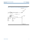
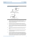
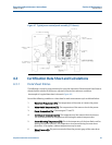
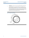
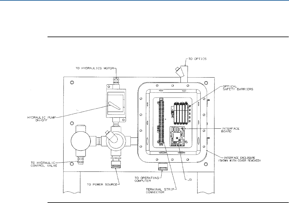
Figure 4-7 Typical prover control panel assembly (12” shown)
4.3 Certification Data Sheet and Calculations
4.3.1 Data Sheet Entries
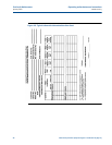
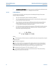
The following is a step-by-step procedure for using the Volumetric Determination Data Sheet to
obtain the base volume of the prover, adjusted (corrected) to reference conditions.
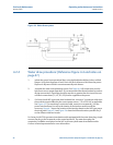
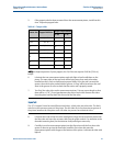
An example of a typical data sheet is shown in Figure 4-6.
Record the following variables on a data sheet for each measurement cycle as defined below:
1. Water Inlet Temperature (T1): The temperature of the water as it enters the prover.
2. Water Outlet Temperature (T2): The temperature of the water as it exits the prover.
3. Prover Temperature (Tp): The average of T1 and T2.
4. Test Measure Temperature (Tm): The temperature of the water in the test measure.
This is measured with the temperature thief during the water draw procedure.
5. Sensor Mounting Temperature (Td): This is the temperature of the Invar Rods used for
spacing the optical switches. The temperature is measured during the water draw
procedure. As an option, ambient temperature may be used.
6. Water Pressure (P): The pressure recorded from the pressure gage of the water draw
system.