


38 Certification techniques
Section 4: Maintenance Operating and maintenance instructions
January 2015 3-9008-701 Rev J
be determined to have an exact volume of 15.00123 or 14.99712 gallons. These types of
numbers are typical and necessary. The particular volume used is determined by the physical
location of the meter under test, either upstream or downstream of the prover. If only one base
volume is used for proving, base volume certification will only need to be completed for the
needed volume and not for both.
The base volume of the compact prover is verified at the factory using test measures that are
traceable to the National Institute of Standards and Technologies (NIST). Additional information
about certification techniques can be found in the American Petroleum Institute (API) manual of
Petroleum Measurement Standards, Chapter 4.2 for Small Volume Provers, Chapter 4.7 for Field
Test Measures, and Chapter 12.2 for Calculation of Petroleum Quantities.
Volume Displacement Certification:
The following procedures describe the compact prover base volume determination using the
water draw method. There are three procedures explained; (a) an Upstream only, (b) a
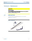
Downstream only, and (c) the Combined method. The measurement piston seal integrity
should be verified prior to any water draw by performing the seal leak check as described in
Section 4.1.
Important:
Before certification is attempted, the prover should be level and isolated from any connecting
piping systems other than those related to the water draw. In choosing the location of the
prover during the test, temperature variations must be considered. Temperatures must be
maintained as stable as possible throughout the operation.
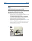
Equipment Required:
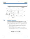
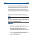
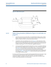
• Water draw hardware kit with manual valves and a solenoid valve similar to Figure 4-3.
For part numbers of factory available water draw hardware kits, see Section 7.
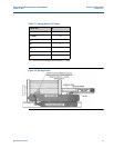
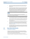
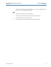
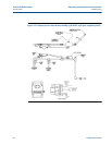
• A plumbing setup as shown in Figure 4-4. Check all valves and any threaded
connections for leaks prior to beginning the water draw procedure. The plumbing
setup must be leak free.
• Certified High Sensitivity (Field Standard) Test Measure traceable to the National
Institute of Standards and Technology (N.I.S.T.) or other certifying agency.
• A water source with a flow rate of approximately 10 gpm (38 lpm) at 30-100 psi (207 to
689 kPa) non-fluctuating and free from entrained air.
• One digital thermometer with contact probe.
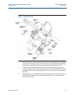
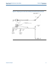
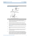
• Three (3) glass stem thermometers with 1/5 degree divisions and a range of 30 to 124.F
(-1 to 50°C), traceable to the National Institute of Standards and Technology (N.I.S.T.)
or other certifying agency, as applicable. One thermometer may be mounted in a
temperature thief device. See Figure 4-5.
• One pressure gauge, 0-100 psig range (689 kPa).