


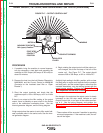
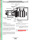

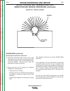
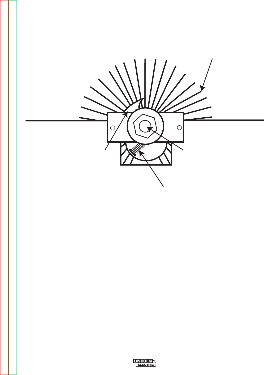
WINDING
Contacts &
Springs
Output Stud
Assembly
Brush
Holder
Assembly
FIGURE F.19 – BRUSH & SPRING
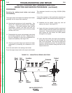
OUTPUT CONTROL UNIT (VARIABLE REACTOR)
INSPECTION AND SERVICE PROCEDURE (continued)
PROCEDURE
1. Turn the engine off, open the doors on the control
panel end of the machine and disconnect the nega-
tive battery cable. The doors must be secured while
disconnecting the battery cable.
WARNING: Secure the doors in the open position
using the door restraint system. If the
machine does not have a door restraint
system, remove the doors or securely
restrain them to prevent them from falling
closed.
2. Remove the roof and doors.
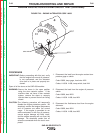
3. Inspect the output control unit:
4. Carefully examine the unit. Check for arc damage,
missing or broken springs, burned and/or badly
worn contacts. Also look for missing or damaged
insulators, poor lead connections, and damaged
lead insulation. If there is serious damage to the
inside diameter of the winding, the Output Control
Unit should be replaced. See Figures F19 and F.20.
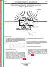
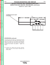
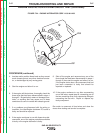
5. Disassemble the continuous control unit:
If service is necessary, remove the fuel tank and dis-
connect the heavy cable attached to the output stud, at
the center back on the output control.
6. Remove the Output control handle.
7. Remove the two screws holding the Brush holder
stud assembly. Use caution, the shaft is under
spring tension. The stud assembly and the rotating
brush holder/contact assembly can now be
removed through the back of the unit. See Figures
F19 and F.20.
TROUBLESHOOTING AND REPAIR
F-60 F-60
SAE-400 SEVERE DUTY
Return to Section TOC Return to Section TOC Return to Section TOC Return to Section TOC
Return to Master TOC Return to Master TOC Return to Master TOC Return to Master TOC