


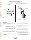
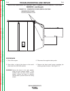
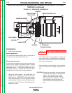
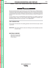

ARMATURE
COMMUTATOR
SPRINGS
BRUSH HOLDER PLATE
BRUSHES
BRUSH RETAINER
BRUSH HOLDER
INSULATORS
MOUNTING SCREW
DRILL MARK
ROCKER
FIGURE F.16 – GENERATOR COMPONENTS
WELDING GENERATOR BRUSH AND COMMUTATOR INSPECTION AND
SERVICE (continued)
PROCEDURE
5. Examine the Commutator.
Normal appearance:
The commutator should appear smooth, and have an
even brown color where the brushes ride.
Blackened Commutator:
A commutator that appears to have an even black color
all around may indicate a grounded armature, shorted
weld circuit, a serious overload condition, or out-of-
adjustment rocker. It could also indicate the use of
poor quality brushes, or brushes that have been conta-
minated with oil or some other foreign substance.
• Check the rocker position. Be certain that it is
aligned with or very close to the factory drill mark.
See Figure 16. IMPORTANT: If the rocker position
requires adjustment, do not over tighten the rocker
clamping screw. This screw should be tightened to
a torque of 70 to 75 Inch-Lbs. Over tightening can
destroy the rocker.
• Perform the Weld Circuit Ground and Short
Circuit Test.
• If the weld circuit is not grounded or shorted, and
poor brush quality or contamination is suspected,
replace the brushes and seat them with a commu-
tator stone or sand paper.
• If brush quality or contamination is not suspected,
clean the commutator by lightly stoning the sur-
face.
CAUTION: Stoning the commutator involves pressing
an abrasive stone against a spinning com-
mutator. This procedure can be haz-
ardous if done without proper training,
tools and protective equipment. Consult
the commutator stone manufacturer’s
instructions before attempting this proce-
dure.
TROUBLESHOOTING AND REPAIR
F-45 F-45
SAE-400 SEVERE DUTY
Return to Section TOC Return to Section TOC Return to Section TOC Return to Section TOC
Return to Master TOC Return to Master TOC Return to Master TOC Return to Master TOC