


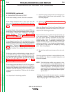


EXCITER ROTOR VOLTAGE TEST (continued)
PROCEDURE (continued)
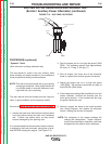
9. Set the RUN/STOP switch to “STOP”
If the meter reading is normal, this test is complete.
If the voltage measures zero or very near zero, the
rotor may be shorting or grounding while spinning.
Perform the Exciter Rotor Resistance and Ground
Test.
If voltage is higher than specified, the engine RPM may
be too high, or there may be voltage intrusion from one
of the higher voltage stator windings to the stator
exciter winding. Perform the Engine RPM
Adjustment Test, and the Exciter Stator Short
Circuit and Ground Test.
If the voltage is lower than 124, but higher than 14, the
engine RPM may be too low, or there may be problems
in the windings or other exciter circuit components or
connections. Perform the Engine RPM Adjustment
Test, and then perform the testing described below,
under the heading “If the voltage measures about 2 to
4 VDC”
If the meter reading indicates battery voltage, about 12
to 14 VDC, The rotor may be opening while spinning,
or the brushes may be faulty or not making proper con-
tact with the slip rings while the rotor is spinning.
Perform the Rotor Resistance Test, and the Brush
and Slip Ring Service Procedure.
If the voltage measures about 2 to 4 VDC, the genera-
tor is not building-up to normal output even though the
flashing circuit appears to be functioning normally. This
condition could be caused by one of several failed
components or connections. Continue with the follow-
ing tests.
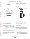
10. Check the D1 field bridge rectifier.
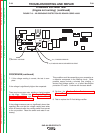
11. Check the wiring and terminals connecting the D1
bridge rectifier to the Exciter stator winding. See
the wiring diagram.
12. Perform the Exciter Stator Short Circuit and
Ground Test.
When the Stator Short Circuit and Ground Tests have
been completed, reconnect the leads to the AC termi-
nals of the D1 field bridge rectifier.
Be sure that there are no loads of any kind across any
of the stator windings. The exciter winding should be
the only stator winding connected at this time.
Examine stator wiring for damage, pinched leads,
chafed insulation, etc. If necessary, disconnect and
insulate the stator output leads as close to the stator
winding as possible. If any leads were disconnected,
secure them so they cannot be damaged by moving
parts. See wiring diagram.
13. Re-start the machine and measure the rotor volt-
age.
If the rotor voltage continues to read significantly lower
than 124VDC, the Stator is probably defective and
should be replaced.
NOTE: The field bridge rectifier may appear to func-
tion normally when tested independently, but
may malfunction when placed under the stress
of normal operation. For this reason, it is rec-
ommended that the bridge rectifier be replaced
with a known good component before replac-
ing the stator.
* Voltages shown in this document are for a machine
operating at normal temperature. Voltage readings
may be slightly higher if the machine is cold.
TROUBLESHOOTING AND REPAIR
F-32 F-32
SAE-400 SEVERE DUTY
Return to Section TOC Return to Section TOC Return to Section TOC Return to Section TOC
Return to Master TOC Return to Master TOC Return to Master TOC Return to Master TOC