


ALTERNATOR STATOR REMOVAL AND REPLACEMENT (continued)
Replacing the Exciter Alternator Stator:
1. During reassembly, anti-seize compound should be
applied to the screw threads.
2. Inspect the mating surfaces of the generator frame
and the exciter bracket assembly. These surfaces
must mate together completely so it is very impor-
tant that the surfaces are completely clean and
undamaged. The bearing and bearing housing
should also be clean and undamaged.
Be sure that the rocker assembly is placed on the bear-
ing housing with the locking screw positioned on top.
3. Place some bearing grease in the bearing housing.
Chevron SRI or equivalent is recommended.
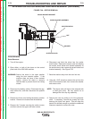
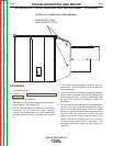
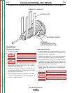
4. Mount the exciter stator/end bracket assembly to
the welding generator frame. Carefully line up the
drill spot between the two mating parts. Carefully
and evenly tighten the four mounting bolts. See
Figure F.31.
5. Check the armature air gap. At the smallest point,
the gap should be wide enough to allow a .030”
thick ½” wide feeler gage to fit between the arma-
ture and stator through the entire length.
6. Position the rocker tightly against the hub, align the
drill mark and tighten the rocker lock screw to 70 to
75 Inch-Lbs. DO NOT OVERTIGHTEN.
7. Be certain that the brush holders are properly posi-
tioned and parallel with the commutator. See the
commutator and brush service procedure.
8. Re-attach the heavy generator leads to the brush
holders. Use the notes made during disassembly to
assure that the leads are connected and routed cor-
rectly.
9. If the original brushes are used, install them in the
same positions that they had been. Form the braid-
ed brush leads so they will not interfere with the
travel of the brushes as they wear.
10. Reverse the removal procedure to finish reassem-
bling the machine.
11. Replace all the tie wraps that had been removed
during disassembly.
12. Replace and connect the batteries. Connect the
positive cables first, followed by the negative
cables.
13. Connect the fuel line and fill the tank. The fuel sys-
tem may require bleeding. See the engine instruc-
tion manual for more information on the fuel sys-
tem bleeding procedure.
14. Start the engine and seat the brushes using a
commutator stone. See the commutator and
brush service procedure.
15. Replace the brush and exciter sheet metal covers.
16. Replace the roof and doors.
TROUBLESHOOTING AND REPAIR
F-84 F-84
SAE-400 SEVERE DUTY
Return to Section TOC Return to Section TOC Return to Section TOC Return to Section TOC
Return to Master TOC Return to Master TOC Return to Master TOC Return to Master TOC