


THEORY OF OPERATION
E-7 E-7
SAE-400 SEVERE DUTY
Return to Section TOC Return to Section TOC Return to Section TOC Return to Section TOC
Return to Master TOC Return to Master TOC Return to Master TOC Return to Master TOC
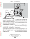
WELDING GENERATOR OPERA-
TION (Continued)
Producing weld current:
Weld current is produced in the armature windings
when it spins in the magnetic field produced by the
excitation process described above. The 64 Ohm rheo-
stat in the excitation circuit varies the strength of the
field. A stronger field will produce greater weld output;
a weaker field will produce less.
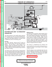
As the windings in the armature pass through the mag-
netic field, current flows, first in one direction, then the
other. This alternating current flow is converted to
direct current (DC) and connected to the remaining
generator circuitry through a commutator and a system
of brushes.
The commutator is a cylindrical structure made up of
copper conductor bars and insulating materials that
keep each bar isolated from the other bars and from
the armature shaft. Each bar is connected to the end
of an armature winding.
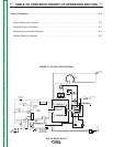
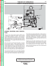
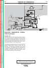
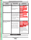
FIGURE E.2 - GENERAL DESCRIPTION
The brushes contact the commutator at precise points
around its circumference and are positioned so that
they will conduct current only from windings that are
producing maximum output at the correct polarity.
With the armature spinning at about 1800 RPM, wind-
ings are coming in contact with the brushes many
times per second, producing a continuous flow of DC
current at the generator brushes.
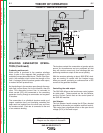
Controlling the weld output:
The SAE-400 utilizes a dual continuous control system
for weld output. These controls are the Job Selector
and the Current Control dials on the control panel of
the SAE-400 machine.
Job Selector:
The Job Selector handle rotates the 64 Ohm rheostat
described in the section on excitation and field control.
This control has a significant effect on the open circuit
voltage (OCV) of the weld output.
DIESEL
ENGINE
THERMOSTAT
INJECTION
PUMP
SOLENOID
SYSTEM
THERMOSTART
BUTTON
IDLE SWITCH
IDLE
SOLENOID
IDLE / ENGINE
PROTECTION BOARD
TO IDLE / ENGINE
PROTECTION BOARD
RUN/STOP
SWITCH
S
T
A
R
T
E
R
TO IDLE/ENGINE
PROT. BOARD
OIL
PRESSURE
SWITCH
TEMP
SWITCH
STARTER
SOLENOID
AMMETER
START
BUTTON
ENGINE
FAULT
LIGHT
HOUR
METER
TO
FLASHING
RESISTOR
AND
DIODE
INTERPOLE COILS
GENERATOR
ARMATURE
SERIES COILS
SHUNT COILS
115 VAC
RECEPTACLES
230 VAC
RECEPTACLES
AUXILIARY
POWER
WINDINGS
EXCITER
WINDING
EXCITER
ROTOR
MIN
(OFF)
MAX
OUTPUT
CONTROL
ELECTRODE
TERMINAL
RESISTOR
POLARITY
SWITCH
REMOTE
RHEOSTAT
LOCAL
RHEOSTAT
(JOB SELECTOR)
TO HOUR METER
FLASHING
RESISTOR AND
DIODE
(+)
(+)
(-)
(-)
AC
AC
(-) (+)
WORK
TERMINAL
TO ALTERNATOR
FLASH/SENSE
TO INJECTION
PUMP SOLENOID
NOTE: Unshaded areas of Block Logic
Diagram are the subject of discussion