


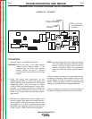
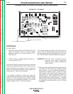

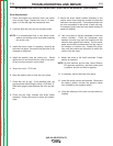


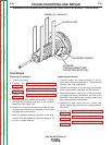
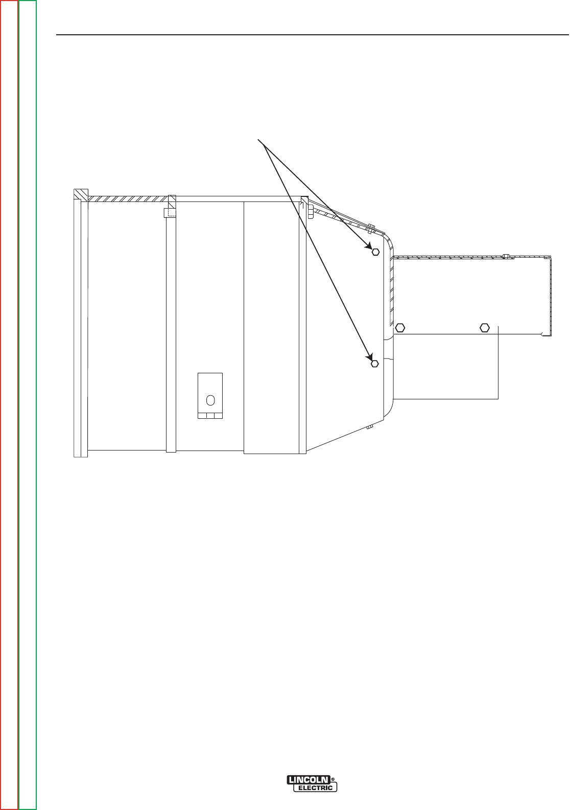
GENERATOR COVER
FOUR SCREWS TOTAL
FIGURE F.30 – GENERATOR COVER REMOVAL
ALTERNATOR STATOR REMOVAL AND REPLACEMENT (continued)
PROCEDURE
1. Turn off the engine.
2. Perform the Alternator Rotor Removal
Procedure.
3. Remove the roof and doors.
4. Remove the four covers protecting the welding gen-
erator brushes. See Figure F.30
5. Use the wiring diagram to identify all of the wires
connected to the alternator stator winding.
Carefully mark these leads, for later reassembly,
and then disconnect them. Cut cable ties as need-
ed.
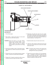
6. Lift the eight welding generator brushes from the
commutator. Note the position of the brushes for
later reassembly.
7. To assure accurate reconnection, carefully mark the
heavy leads connected to the brush holders, and
then disconnect them. To aid in reassembly, note
the way these leads are connected, routed, and
positioned.
8. The front panel of the machine can be unbolted and
moved to the side to provide the clearance neces-
sary to remove the exciter stator. This can normally
be done by disconnecting only the wires and cutting
only the cable ties necessary to allow the front
panel to be moved. Most wiring can remain con-
nected. Be sure to carefully mark all of the wires
that were disconnected to aid in reassembly. The
emergency shut down cable will also need to be
removed.
TROUBLESHOOTING AND REPAIR
F-82 F-82
SAE-400 SEVERE DUTY
Return to Section TOC Return to Section TOC Return to Section TOC Return to Section TOC
Return to Master TOC Return to Master TOC Return to Master TOC Return to Master TOC