


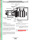

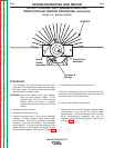
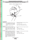

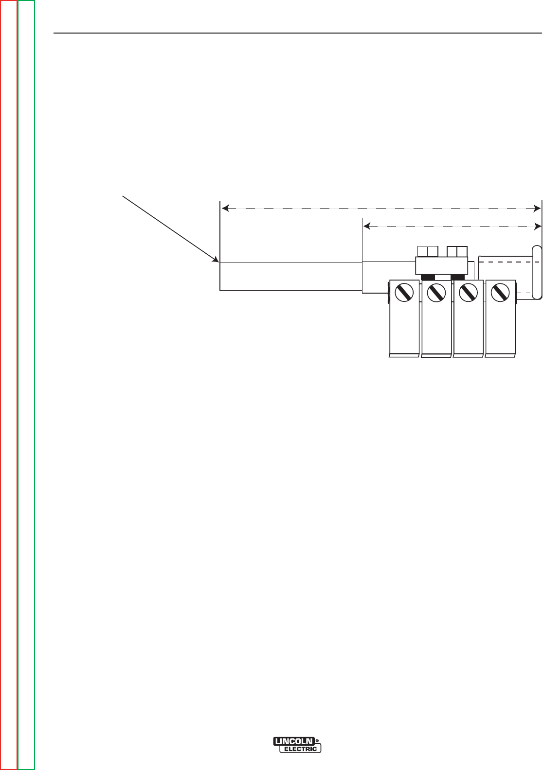
FIGURE F.22 – SHAFT & TUBE
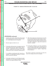
OUTPUT CONTROL UNIT (VARIABLE REACTOR)
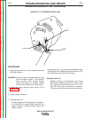
INSPECTION AND SERVICE PROCEDURE (continued)
PROCEDURE (continued)
The shaft spring will need to be compressed and the
bracket drawn close to the back of the output control
before the screws can be started and tightened.
Locking type pliers and a drift punch can be used to
maneuver the bracket into position. Tighten the
screws.
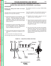
16. Connect any cables that had been removed.
Install fuel tank, roof and doors. Reconnect the
battery cable.
TROUBLESHOOTING AND REPAIR
F-63 F-63
SAE-400 SEVERE DUTY
Return to Section TOC Return to Section TOC Return to Section TOC Return to Section TOC
Return to Master TOC Return to Master TOC Return to Master TOC Return to Master TOC
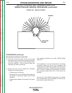
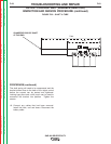
CHAMFERED END OF SHAFT
AT THIS END
7
5/8”
4
1/4”