


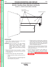
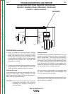
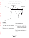
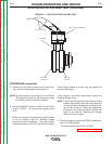

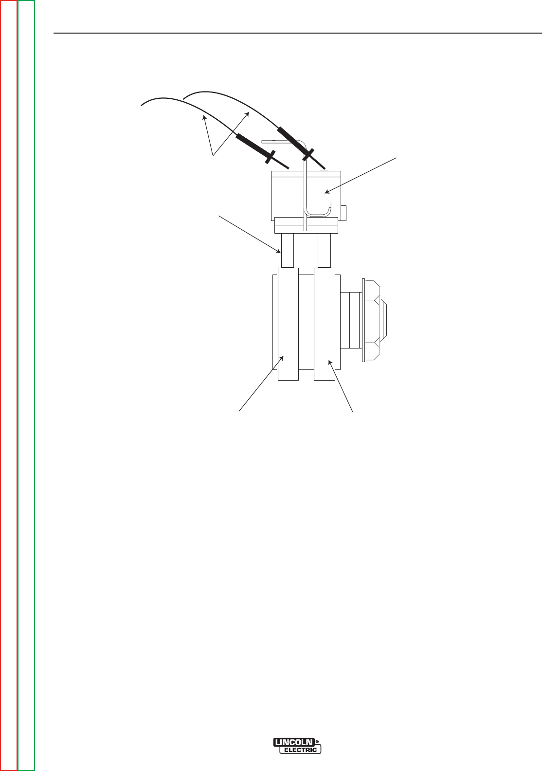
POSITIVE
SLIP RING
NEGATIVE
SLIP RING
BRUSH HOLDER ASSEMBL
Y
BRUSHES
VOLTMETER LEADS
FIGURE F.7 – EXCITER ROTOR VOLTAGE TEST
EXCITER ROTOR VOLTAGE TEST (continued)
PROCEDURE (continued)
5. Connect the volt meter probes to the brush termi-
nals. See the wiring diagram and Figure F.7
NOTE: On this machine, and all other Lincoln Electric
DC generator machines, the black exciter lead
is positive, and the red lead is negative.
6. Set the RUN/STOP switch to “RUN” and the IDLE
switch to “HIGH”. Do not start the engine at this
time.
7. Within 30 seconds of switching the run/stop switch
to the run position, read the “flashing” voltage
across the brush connections. The meter should
read approximately 2 to 4 VDC. (Check this voltage)
If this voltage reading is correct, start the engine and
continue the testing.
If this voltage is not within these limits, perform the
Flashing Voltage Tests.
NOTE: If more than 30 seconds (One minute for some
models) has passed, the engine fault lamp will
turn on and the fuel solenoid and flashing volt-
age will be turned off. Before the engine can
be started, the engine protection system will
need to be reset by switching the run/stop
switch off, then on again.
8. Start the engine and allow the RPM to stabilize for
about 15 to 30 seconds.
The meter should read 124 to 132 VDC*.
(continued on following page)
TROUBLESHOOTING AND REPAIR
F-31 F-31
SAE-400 SEVERE DUTY
Return to Section TOC Return to Section TOC Return to Section TOC Return to Section TOC
Return to Master TOC Return to Master TOC Return to Master TOC Return to Master TOC