


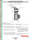
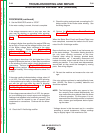
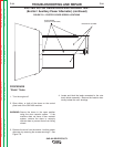
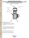
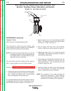

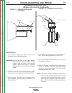
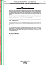
POSITIVE
SLIP RING
NEGATIVE
SLIP RING
BRUSH HOLDER ASSEMBL
Y
BRUSHES
VOLTMETER LEADS
FIGURE F.10 – SLIP RING LOCATIONS
EXCITER ROTOR RESISTANCE AND GROUND TEST
(Exciter / Auxiliary Power Alternator) (continued)
PROCEDURE (continued)
“Dynamic” Tests:
(Also referred to as flying resistance test)
This test checks for faults in the rotor winding, while
these windings are being stressed by the mechanical
forces encountered during normal operation.
NOTE: This test is best performed with a good quality
analog type ohmmeter. Many digital meters will
not provide stable or accurate resistance read-
ings while the rotor is spinning.
This test requires that the brushes and slip rings are
clean, in good condition, and are properly seated.
Perform the Brush and Slip Ring Service Procedure.
1. Insulate the lead wires that had been disconnected
from the brushes during the static rotor resistance
test. Position and secure them so they cannot
become damaged by the spinning rotor.
It is recommended that the ohmmeter leads be secure-
ly attached to the brush terminals, using clips or termi-
nals BEFORE starting the engine. See Figure F.10.
2. Start the engine and run it at high idle speed (1800
RPM). The resistance should read approximately
42 ohms* at 77 deg. F. (25 deg. C).
3. Shut off engine, and move one of the ohmmeter
leads to a good clean chassis ground connection.
4. Restart the engine and run it at high idle speed
(1800 RPM). The resistance should be very high, at
least 500,000 (500k) ohms.
5. If the resistance readings differ significantly from the
values indicated, re-check the brushes and the
brush spring tension. If the brushes and slip rings
are good, replace the rotor.
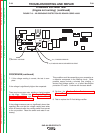
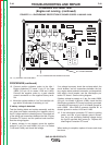
6. Securely connect the leads to the brush terminals
(see wiring Diagram) and replace the alternator
covers if testing and service is complete.
*NOTE: The resistance of the copper windings will
change with temperature. Higher tempera-
tures will produce higher resistance, and lower
temperatures will produce lower resistance.
TROUBLESHOOTING AND REPAIR
F-36 F-36
SAE-400 SEVERE DUTY
Return to Section TOC Return to Section TOC Return to Section TOC Return to Section TOC
Return to Master TOC Return to Master TOC Return to Master TOC Return to Master TOC